
| People |
| Michael |
| Meredith |
| Matthew |
| Jacob |
| Emily |
| Dave |
| Stevie |
| Lauren |
| Places |
| Cape Cod, MA 79-83 |
| New York, NY 83-88 |
| Mobile, AL 88-93 |
| Savannah, GA 93-98 |
| Atlanta, GA 96-01 |
| Savannah, GA 01-02 |
| Pensacola, FL 03-04 |
| Savannah, GA 04-09 |
| Mobile, AL 09-13 |
| Savannah, GA 13-16 |
| Washington, DC 16-20 |
| New Orleans, LA 20-22 |
| Savannah, GA 22-24 |
| Miami, FL 24- |
| _________________ |
| New Orleans, LA 98-00 |
| Londonderry, NH 00-02 |
| Cape Cod, MA 02-05 |
| New London, CT 05-08 |
| Merrimack, NH 08- |
| Links |
| Pools |
| Coding Challenges |
| Image of the Month |
| Flight School |
| Vegas Walk! |
#
360° overhead approach
40 degree lock-off A
ABNORMAL STARTS
ADF characteristics and limitations
AFCS failure
AFCS/force trim
AFCS requirements for IMC flight
Air taxi vs. hover taxi
Aircraft discrepancy book
AIRFIELD INFORMATION AVAILABLE IN IFR/VFR SUPPLEMENT
Airframe fuel filter/fuel contamination
Airport lighting (to include pilot controlled lighting)
Airspace
Airspeed limits
Altimeter error
Altitude restrictions when cleared for approach
ANTI ICE OPERATION
Approach brief
APU START
Attitude gyro-malfunction (IMC)
Attitude instrument flight/trim/scan
Autorotation
AUTOROTATION INTO THE TREES
Autorotation night power recovery
Autorotative aerodynamics B
Back course localizer procedures
BALDY-1 Departure
Base Recovery Course (BRC) and Foxtrot Corpen
Basic instrument syllabus
Battery relay light
Battery system and malfunctions
Blade element diagram
Blowback (normal approach/transition to forward flight)
Boost-off approach
Brevity Codes C
CAT II/III ILS
CAUTION SYSTEM
CHARLIE and DELTA patterns
Chart Preparation for night navigation
COLD WEATHER LIMITATIONS
Combat cruise, section low-level flight/navigation
Compass locator
COMPRESSOR STALL
Cone of confusion
Confined Area Takeoffs and Landings (CALs)
Contact approach
Control feedback
Control points and checkpoints
Copter procedures
Course receiver failure
COURSE RULES (CHOCTAW)
COURSE RULES (DUKE)
COURSE RULES (Harold OLF)
COURSE RULES (SANTA ROSA)
Crew comfort levels
Crew coordination: during emergencies
Crew coordination: Instrument approach responsibilities PNAC
Crew coordination: integration of aircrew
Criteria for continuing an instrument approach to landing
CRM
CRM and interaircraft communication
CRM (adaptabilty/flexibility)
CRM (assertiveness)
CRM (as it relates to low level navigation)
CRM (communication)
CRM (decision making)
CRM (leadership)
CRM (mission analysis)
CRM (Night Flying)
CRM (situational awareness)
Cruise position, cruise maneuvers and brevity codes D
Dark adaptation
DD-175 & DD-175-1
Deck spotting
Departure Procedures
DIF ON EARLY AND LATE 57B
Disorientation procedures
Dissymmetry of lift
DITCHING
DOT COM'S 2 cents on HTACs
DOT COMs 2 cents on RI Simulator Check Ride (RI-09X)
Duct high temp caution light
DYNAMIC ROLLOVER E
ECS system/malfunctions
Effects of adverse weather on mission planning
Electrical system/malfunctions
ELVA approaches (Emergency Low Vis Approach)
Emergency at low altitude
Emergency descent
EMERGENCY ENGINE SHUTDOWN
Emergency procedures/Landing site evaluation at night
EN ROUTE EMERGENCY DIVERT FIELDS
En route/feeder routes
EN ROUTE LOW ALTITUDE CHART SYMBOLS
Engine chip clearing procedures
ENGINE FAILURE
Engine failure with external load
Engine failures night
Engine failures NATOPS/FTI
ENGINE OIL SYSTEM MALFUNCTIONS
ENGINE OVERSPEED (Nf) ROTOR RPM (Nr)
ENGINE UNDERSPEEDING Nf OR Ng (LOW Nr)
ENGINE RESTART IN FLIGHT
Engine system
Environmental conditions encountered in TLAs to include: sand, dust, and snow
Equipment malfunction reports
Execute missed approach
Expected further clearance
External load ops F
Failed directional gyro NDB procedures
Failed directional gyro PAR approach
Failed directional gyro TACAN approach
FDLP takeoff/landings
Field deck landing practice (FDLP) pattern and airspeeds
Fire during IMC flight (Engine, electrical, fuselage)
Flight control system
Flight in restricted visibility over water
Flight Information Handbook
FLIGHT LINE OPERATIONS (TAXI SIGNALS)
Flight maneuvers in the TH-57C
Fly-by vs. Fly-over waypoints
Fuel system
FUEL SYSTEM MALFUNCTIONS G
GCA lost communications
GCA procedures
Geometric imbalance
Glideslope failure
GPS
GPS missed approach
Ground vortex H
HAA/HAT/HAL
Helicopter Point-In-Space (PinS) Approach
Helicopter preparation for night operations
High speed approach
High Speed Low Level Autorotation (DEMO ONLY)
HOSTAC
Hot seat/hot refuel checklist and procedures
Hot seat procedures
Hover
Hovertaxi
HSI or CDI failure
Hydraulic power cylinder malfunction
HYDRAULIC SYSTEM
Hydraulic system failure I
Icing
ILS procedures
Inadvertent IMC at low level
Inadvertant IMC on night route
Inadvertant IMC over water
Initial radio contact with ATC
Inoperative Components or Visual Aids Table
Instrument approach/communications at uncontrolled airports
Instrument autorotation
Instrument Takeoff (ITO)
Instrument takeoff (ITO) checklist J
Jammed flight controls
JOG AIR preparation L
Land as soon as possible
Land as soon as practicable
Landing criteria for emergencies/definitions
Landing zone lighting
Lead and wing aircraft responsibilities and considerations
Level speed change (BIs)
Level speed change (FAMs)
Level standard rate turns
Leveloff checklist
LIMITATIONS
Localizer procedures
LOST COMMUNICATIONS EN ROUTE
Lost communication - NDZ on top
Lost communication procedures at the boat
Lost communication procedures on IFR flight plan
Lost communication while being radar vectored
Lost plane procedures
Low fuel state during IMC flight
Low level navigation at night
Low level scan using Radar Altimeter
Low RPM recovery
LSE signals M
Magnetic compass turns
MAIN DRIVE SHAFT FAILURE
Maneuver complete reports
Marker beacons
MAST BUMPING
Maximum glide auto
Maximum load takeoff
Mechanical versus virtual axis
Minimum safe altitudes/emergency safe altitudes
Minimum Vectoring Altitude
Ministab operation
Missed approach from DH/MDA/circling
MOCA/MCA/MRA N
NATOPS CLOSED BOOK EXAM
NDB bearing intercepts (inbound, outbound, wingtip, over the station)
NDB orientation
NDZ departure
NDB station passage
NDZ on top clearance/ NDZ airwork clearance
NDZ on top weather briefing
NDZ stereotype flight plans
Night autorotations
Night ground procedures
Night hover/hover taxi
Night hover scan
Night visual flight techniques
No-hover landing
No hover takeoff
Normal Approach
NOTAMS, Class (I) and (II), D, L, FDC/NOTAM codes
NWP 3-04.1 O
OPNAVINST 3710.7
Option approach
Oscar Pattern
Overhead time
OVERTORQUE/OVERTEMP/OVERSPEED
Overlay approach P
PAN/MAYDAY REPORTS
Parade break at homefield
Partial panel ASR approach
Partial panel straight and level
Partial panel turns
Phase lag
Pilotage, Dead Reckoning, and Radio navigation techniques
Pinnacle takeoff and landings
Pitot-static instrument failure
Pitot-static instruments, alternate static source
POST SHUTDOWN FIRE/INTERNAL
Power checks
POWER REQUIRED EXCEEDS POWER AVAILABLE
POWER SOURCE FOR ALL GAUGES
Practice approaches VFR/IFR
Precision minima
Precision navigation using the Global Positioning System
Preflight and in-flight fuel planning
PREFLIGHT EXTRAS IN THE TH57-C
Preparing for an instrument approach
Prohibited Maneuvers
Prohibited solo maneuvers
Pubs carried on BI flights Q
Quick Stop
Quick stop from a hover R
Radar Altimeter Failure
Relative motion and radius of turn relationship
Required equipment for IMC
Required equipment for night flight
Required voice reports
Retreating blade stall
Reverse sensing (CDI and HSI)
ROTOR BLADE STALL
Rotor droop
RPM BEEP CONTROL S
SAR
SAR Patterns
Section high speed approach
Section parade
Section waveoff
Ship NAVAIDS
Shipboard Approach
Shipboard Aviation Facilities Resume
Shipboard terminology
Ships communication, NAVAID frequencies and identification
Sidestep maneuver
Simulated emergencies at altitude (not to include tail rotor malfunctions)
Simulated engine failure at altitude (at and away from site)
Simulated engine failure hover/hover taxi (cut gun)
Simulated engine failure on takeoff (DEMO ONLY)
Simulated fixed pitch tail rotor at altitude (stuck right and left)
Simulated stuck pedal in a hover (right and left)
Simulated tail rotor failure in a hover (complete loss of tail rotor thrust)
Sliding Landing
SMOKE AND FUME ELIMINATION
Solo observer responsibilities
Solo weather minimums for ANs
Sources of weather information
Special VFR
Special VFR course rules (at NDZ)
SPRAG CLUTCH MALFUNTION
Square patterns
Stab/trim failure at low altitude
Stab off approach
Standby battery
Standby generator minimum airspeed
Standard instrument rating requirements
Standard rate climbs and descents
Standard Terminal Arrival (STAR)
STARTER LIMITS
Steep approach
Straight and level flight
Straight-in approach/circle to land
SUSPECTED FUEL LEAKAGE T
TACAN
TACAN approach
TACAN approaches (LHA/CV)
TACAN approaches to air capable ships (DD, AE)
TACAN arcing
TACAN ground speed check
TACAN holding (station and non-station side)
TACAN missed approach
TACAN orientation
TACAN point-to-point navigation
TACAN radial intercepts
TACAN tracking
TACH/GEN MALFUNCTIONS
Tactical Landing Area (TLA) selection criteria
Tail rotor malfunctions and failures
Takeoff/Approach/landing minimums (RWOP/3710.7)
TERF profiles
Terminal Arrival Area (TAA)
Terminal procedures
TORQUE MALFUNCTIONS
TOT MALFUNCTIONS
Transition to forward flight
TRANSMISSION OIL SYSTEM MALFUNCTIONS
Transmission system
Turbulence penetration
Turn on the spot/clearing turns
Turn Pattern U
Uncommanded right roll during flight below 1 G
Unusual attitude recoveries (full panel)
Unusual attitude recoveries (Partial panel)
Use of GPS during SAR
Use of lights
USE OF LIMITS
Use of metro, FSS, and flight watch facilities
Use of radar altimeter V
VASI/PAPI lights
Vertical landing
Vertical S-1 pattern
Vertical takeoff
Vertigo parameters
Vertigo/Two challenge rule
VFR filing and flight procedures
VIBRATION IDENTIFICATION
Visual approach
Visual scanning
VOICE REPORTS
VOR
VOR holding
VOR orientation
VOR receiver checks (airborne, ground)
VOR station passage
VOR tracking
VORTEX RING STATE W
Wave off (during CALs)
Wave off (during externals)
Wave off (power off)
Waveoff (power on)
Weather brief requirements
Weather briefing and minimums (DD-175-1)
Weather requirements for BI flights
Windline Rescue Pattern
Wing awareness/lookout doctrine
WW/CAWW/Convective SIGMET/SIGMET/AIRMET 360° overhead approach
1) Initiate directly over or slightly before landing point at 100 AGL and 80 KIAS, commence a smooth coordinated turn utilizing 30 to 60 degrees AOB to arrive at 180 ° position at 100 AGL
2) From the 180 ° position continue to level turn and begin decelerating to arrive at the 90 ° position with 100 AGL and 70 KIAS
3) From the 90 ° position continue the decelerating level turn to intercept courseline with 100 AGL 45 to 65 KIAS. Visualize the glideslope and rate of closure to the intended point of landing. Approach angle should not exceed 45 °
4) Maintain balanced flight throughout the pattern until intercepting the courseline.
5) Rate of closure and descent are controlled to arrive over intended point of landing in no-hover or hover with zero groundspeed.
RADALT IS UNRELIABLE IN STEEP AOB 40 degree lock-off
TACAN is susceptible to azimuth errors of 40 ° or multiples thereof (i.e. 80 °, 120 °, etc.). This may be caused by a weak airborne receiver and rectified by merely rechannelizing the unit. ABNORMAL STARTS
STARTER FAILURE
* STARTER OFF
If Ng rose but never got 15% then get APU. No rise may indicate bad starter.
IGNITER FAILURE
TOT does not rise after twist grip is rotated to flight idle, Ng does not rise above 20 percent
Procedure:
*TWIST GRIP CLOSE
*FUEL VALVE OFF
*STARTER SECURE
*BAT Switch OFF (when Ng is zero)
HUNG START
Ng rises slowly and stabilizes below 50%, TOT rises more slowly than normal
Procedure:
*TWIST GRIP CLOSE
*FUEL VALVE OFF
*STARTER SECURE after TOT stable below 400
*BAT Switch OFF
HOT START
TOT exceeds limits, TOT digital display and TOT caution light flashes (twice per second)
NOTE: any of the following could indicate a hot start:
Excessive rise in TOT
TOT accelerates through 840 degrees
Battery voltage stabilized below 17 volts when starter is engaged.
Procedure:
*TWIST GRIP CLOSE
*FUEL VALVE OFF
*STARTER SECURE after TOT stable below 400
*BAT Switch OFF
ENGINE FIRE ON START/EXTERNAL
Fire Warning Light, Smoke, Fire, Indications from Fire Guard
Procedure:
*TWIST GRIP CLOSE
*FUEL VALVE OFF
*BAT Switch OFF
*ROTOR BRAKE ENGAGE (Charlie model only)
*HELICOPTER EXIT and use fire bottles or get clear.
*WARNING!!! Beware of rotor blades after exiting A/C
ABORT START
When any abnormalities are encountered during the start sequence
Procedure:
*TWIST GRIP CLOSE
*STARTER SECURE after TOT stable below 400
*BAT Switch As required ADF characteristics and limitations
Normally used as backup navigational aids.
Helicopters operating in remote areas use as primary means of radio nav.
Range is beyond line of sight so good for low flying helicopters.
DIP ERROR: causes erroneous bearing indications in turns. Turns must be made to predetermined headings. (cuz of loop style operation)
Bad weather (lightning etc)
ADF does not have a flag to warn pilot, therefore must continuously monitor the NDB id to ensure proper reception. Noisy ID may be heard when a steady false bearing is being displayed. Music, voice, etc.
HH=2000watts or more (75NM)
H=50-2000watts (50NM)
MH=50watts or less (25NM)
190 to 535 KHz
Loop Antenna
TH57 KR-87 recieves LF/MF reception 200-1799 KHz
No CDI so, crab angles must be tested and updated. AFCS failure
Pitch and Roll are located on FCS Inverter while Yaw is located on the Avionics inverter.
FCS Inverter Failure
INDICATIONS: FCS light flashes, Loss of pitch/roll servos, Loss of FCS
PROCEDURES:
NOTE: Force Trim will function
If FCS inverter voltage is less than 111 volts:
FCS CB (ESS-1 lower panel) PULL
Establish VMC
Avionics Inverter Failure
INDICATIONS: AC voltage drop, RMI needles fail in VOR, Yaw servo fails
PROCEDURES:
AVIONICS INVERTER CB (ESS-2 upper panel) PULL
NOTE: Further IMC flight possible but is now without RMI and yaw servo AFCS/force trim
Basic three axis system with force trim designed to provide attitude retention and to smooth pilot inputs to the controls. It also provides altitude hold in cruise (above 40kts). Pitch and roll actuators are located at top of control tubes which provide input to hydraulic servo pilot valves. Pitch and roll computers provide signal to actuators to move about the neutral point. (0.5 inches or 1.0 inches according to NATOPS or systems book)
Yaw actuator is connected to tail rotor control tube and since it is not hydraulic, it is larger and has a temperature cutoff switch. AFCS requirements for IMC flight
Equipment required for IMC flight (AFCS portions):
Mini Stab flight control system (pitch and roll)
Cyclic force trim Air taxi vs. hover taxi
Air Taxi = <100AGL, >20 knots
Hover Taxi = in ground effect < 20 knots. Aircraft discrepancy book
Daily = 72 hours
Turnaround = 24 hours
10 flights + anything not fixed
Left (yellow) fixed
Right (pink) unfixed Airfield information available in IFR/VFR supplement
Section B contains an alphabetical listing of all: Airports (landplane and heliports) which meet one of the below listed criteria; Air Traffic Control Centers; Flight Information Centers; Communications Stations; and Radio Aids to Navigation.
Selection criteria for Airports and Facilities (must have at least one):
(1) A published DoD Instrument Approach Procedure and/or approved RADAR minima.
(2) Those airports published on En route Charts in accordance with applicable specifications.
(3) Those airports or heliports with an arrival or departure procedure or a directory entry published in the VFR Arrival/Departure Books.
(4) At least one 3000' or longer runway of hard surface where landings of DoD aircraft are not specifically prohibited.
(5) Specifically requested by a DoD unit to meet operational requirements.
(6) Heliports operated by a DoD military service, or requested by a DoD military service to meet operational requirements. Airframe fuel filter/fuel contamination
 Airport lighting (to include pilot controlled lighting)
Runway edge lights are used to outline the edges of runways during periods of darkness or restricted visibility conditions. These light systems are classified according to the intensity or brightness they are capable of producing: they are the High Intensity Runway Lights (HIRL), Medium Intensity Runway Lights (MIRL), and the Low Intensity Runway Lights (LIRL). The HIRL and MIRL systems have variable intensity controls, whereas the LIRLs normally have one intensity setting.
The runway edge lights are white, except on instrument runways yellow replaces white on the last 2,000 feet or half the runway length, whichever is less, to form a caution zone for landings.
The lights marking the ends of the runway emit red light toward the runway to indicate the end of runway to a departing aircraft and emit green outward from the runway end to indicate the threshold to landing aircraft.
Runway Centerline Lighting System (RCLS): Runway centerline lights are installed on some precision approach runways to facilitate landing under adverse visibility conditions. They are located along the runway centerline and are spaced at 50-foot intervals. When viewed from the landing threshold, the runway centerline lights are white until the last 3,000 feet of the runway. The white lights begin to alternate with red for the next 2,000 feet, and for the last 1,000 feet of the runway, all centerline lights are red
VASI (Visual Approach Slope Indicator):
Visible from 3-5 miles during day, up to 20 miles at night.
Provides safe obstruction clearance within plus or minus 10 ° of extended runway
Most installations consist of 2 bars, near and far, providing 3 degree glide path.
Red over white: on glide path.
PAPI (Precision Approach Path Indicator):
Similar to the VASI but are installed In a single row.
Red lights coming in from the right to tell how high above or how low the approach is Airspace
Two categories:
1)Regulatory (A, B, C, D, E, Restricted, Prohibited)
2)Nonregulatory (MOAs, Warning areas, alert areas, controlled firing areas.)
Within those two are the four types:
1)Controlled
2)Uncontrolled
3)Special use(W CAMPR)
Warning area: An airspace extending from 3NM outward from the coast that contains hazardous activity to nonparticipating aircraft. Purpose is to warn non participating aircraft.
Controlled Firing Areas: Contain activities which could be hazardous to nonparticipating aircraft (not on charts, they stop when we enter)
Alert Areas: Depicted to inform nonparticipating aircraft of areas containing high volumes of pilot training or unusual aerial activity.
MOA: separate military training activities from IFR traffic.
Prohibited Area: Established for security or other reasons associated with national welfare.
Restricted Area: Subject to restrictions. Unusual often invisible hazards. ATC will allow you though if not active.
4)Other (MAN TVTP)
Military Training Routes: low altitude, high-speed military operations to be flown mostly under IFR. Routes at 1500AGL and below usually VFR. Generally established below 10000MSL for speeds > 250KTS. 2 types IR and VR. VR needs 5 miles of visibility and 3000AGL ceiling. 4 digits means all under 1500AGL."
Airport Advisory/Information Services (provide advisories) request 60days prior
LAA (10 SM with no control tower, but an FSS)"
RAA (10 SM with no control tower high GA activity)
RAIS (short term special events like small to medium flyins.)
National Security Areas: Locations where there is a requirement for increased security and safety of ground facilities. Pilots are requested to avoid voluntarily but if the case may be, it could become temporarily prohibited."
TRSA (Terminal Radar Service Area): Being replaced, voluntary participation, primary airports are D"
VFR Routes:
Flyways: general flight path not defined as a specific course, for use by pilots in planning flights into, out of, through or near complex terminal airspace to avoid B airspace."
Corridors: airspace through B with defined vertical and lateral boundaries. A hole through B
Transition routes: Routes through B that require ATC assigned altitude and clearance.
Temporary Flight Restrictions: Natural Disasters, Presidential travel, etc."
Parachute Jump Aircraft Operations: DUH MSL
Designation (A, B, C, D, E, G)"
A:
Generally 18000MSL up to and including FL600 out to 12NM of the 48 states and Alaska; and designated international airspace beyond 12NM within areas of domestic radio navigational signal or ATC radar coverage, and within which domestic procedures are applied."
Must have to enter:
Operate under IFR
Weather for VFR ops:
Operate under IFR
B:
Generally surface to 10000MSL surrounding nations busiest airports. Configuration is individually tailored to the airport.
Must have to enter:
ATC clearance
Operable two way radio capable of communicating with ATC
Private pilots certificate required to take off and land at 12 of the class B airports
Private pilots certificate/student pilot cert required for operations in B.
VOR or TACAN for IFR operations
Mode C transponder (exceptions need one hour submitted proposal)
Weather for VFR ops:
3 SM, Clear of clouds"
ATC Clearances and Separation:
VFR A/C are separated from VFR/IFR A/C weighing 19000lbs or less by min of:
Target resolution, or"
500 feet vertical separation, or"
Visual separation
VFR A/C are separated from VFR/IFR A/C weighing > 19000lbs by a min of:
1 ½ miles lateral separation, or"
500 feet vertical separation, or"
Visual separation.
B Mode C veil:
Airspace within 30NM of most B airports from surface to 10000 feet.
Must have to enter:
Mode C transponder (unless certified a/c without it)
C:
Generally surface to 4000AGL (charted in MSL) surrounding those airports that have an operational control tower, are serviced by a radar approach control, and that have a certain number of IFR operations or passenger enplanements. Usually consists of a 5NM radius core surface to 4000AGL and a 10NM shelf from 1200AGL to 4000AGL. Outer area normal radius is 20NM and extends the limits of radar/radio coverage up to the ceiling of the approach controls delegated airspace, excluding Class C and other airspace."
Must have to enter:
No specific certification is required
Two-way radio
Operable mode C transponder. Even when above C up to 10000
Two-way radio comms must be established (when ATC uses your callsign)
Airspeed:
Must be <200KIAS at or below 2500AGL within 4NM of the C airport.
Weather for VFR ops:
3 SM, 500 below, 1000 above, 2000 horizontal (3,5,1,2)"
ATC Clearances and Separation:
Visual separation.
500 feet vertical; except when operating beneath a heavy jet.
Target resolution.
D:
Generally surface to 2500AGL (charted in MSL) surrounding those airports that have an operational control tower. Usually 4.4NM radius (5SM). Also, arrival extensions that are 2 miles or less."
Must have to enter:
No specific certification is required
Two-way radio
Two-way radio comms must be established (when ATC uses your callsign)
Airspeed:
Must be <200KIAS at or below 2500AGL within 4NM of the D airport.
Weather for VFR ops:
3 SM, 500 below, 1000 above, 2000 horizontal (3,5,1,2)"
ATC Clearances and Separation:
None provided.
E:
Generally controlled airspace that is not A, B, C, or D. Extends up from either the surface or a designated altitude to the overlying or adjacent controlled airpace."
Must have to enter:
No specific certification is required
No specific equipment is required
No specific requirements
Types: (SET FOOD)
1. Surface area designation for an airport
Configured to contain all instrument procedures.
2. Extension to a surface area:
Serve as extensions to Class B, C, D surface areas. Provides controlled airspace to contain instrument procedures without imposing comms requirement on VFR pilots."
3. Airspace used for Transition:
Beginning at either 700 or 1200AGL to transition from terminal to enroute
4. Federal airways:
1200 feet to 17999MSL (Domestic, Alaskan, Hawaiian)"
5. Offshore airspace areas:
Provide controlled airspace beyond 12 miles where there is a requirement to provide IFR en route ATC services.
6. Other:
Unless otherwise noted, begins at 14500MSL to 17999MSL with 12 miles from coast of 48 states, DC, and Alaska."
Airspace above FL600 Excluding below 1500AGL unless otherwise noted.
7. En route Domestic areas:
Provide controlled airspace in those areas where there is a requirement to provide IFR en route ATC services but the airway system is inadequate.
Weather for VFR ops:
Less than 10000MSL: 3 SM, 500 below, 1000 above, 2000 horizontal (3,5,1,2)"
At or above 10000MSL: 5 SM, 1000 below, 1000 above, 1SM horizontal (5,1,1,1)"
ATC Clearances and Separation:
None provided
G:
That portion of airspace that has not been designated as A, B, C, D, or E"
Weather for VFR ops:
1200AGL or less:
Day: 1 SM, Clear of clouds"
Night: 3 SM, 500 below, 1000 above, 2000 horizontal (3,5,1,2)"
>1200AGL to 10000MSL:
Day: 1 SM, 500 below, 1000 above, 2000 horizontal (1,5,1,2)"
Night: 3 SM, 500 below, 1000 above, 2000 horizontal (3,5,1,2)"
>1200AGL and >10000MSL: 5 SM, 1000 below, 1000 above, 1SM horizontal"
Other info:
Must remain 1000 (2000 in mountainous) above highest obstacle within 4NM
Airspeed limits
continuous=0 to 130kts
max=130kts
maxauto=100kts (72 range, 50 endurance)"
Sideward/Rearward
25/15 when 0-1000DA
20/15 when 1000-2000DA
15/15 when 2000-4000DA
10/10 when 4000-6000DA
5/5 when 6000-10000DA
Maxrateofclimb 50kias
Min IFR speed 65kias
Max speed AFCS OFF:
3000lb and below: 130kias (decr 3.5kias per 1000ft above 3000ft DA)
3001lb and above: 122kias (decr 7.0kias per 1000ft above 3000ft DA)
Max speed AFCS ON or IFR
3000lb and below: 122kias (decr 3.5 per 1000ft above 3000ft DA)
3001lb and above: 122kias (decr 7.0 per 1000ft above 3000ft DA)
Max speed doors off: 110kias
Turbulence penetration A/S 80kias to reduce airframe stress and provide easier control. Altimeter error
Altimeter error with current barometric pressure set should not exceed 75 feet from known field elevation
Pitot-Static Instruments.
If the airspeed, vertical speed, or altimeter fluctuates erratically or gives apparently false indications while power and attitude instruments are normal, proceed as follows:
1. PITOT HEAT switch(s) - On.
Monitor cruise power settings and nose attitudes to maintain altitude and airspeed. If pitot heat does not remedy the situation, accomplish the following:
2. (C) Alternate static source knob - Pull.
3. Land as soon as practicable. Altitude restrictions when cleared for approach
If on an airway enroute to the IAF (IAF is on the airway) and Cleared for the Approach you may descend to the higher of MEA, MOCA, or the IAF Altitude. If on a feeder route you may descend to the feeder route altitude when cleared for the approach.
If holding at a published holding pattern and you are cleared for the approach you may descend to the published holding altitude once you are cleared for the approach.
When given an approach clearance which contains an altitude restriction you must maintain that altitude, or if no altitude is specified and you are not on a published route (airway or feeder route) you must maintain your current altitude until established on a segment of the IAP.
Remember when you leave an altitude that is not on the approach plate anywhere, it is a required call to tell approach control that you are leaving that altitude. ANTI ICE OPERATION
Operation of Engine during icing conditions could result in ice in compressor restricting air flow and decreasing engine performance. Anti Icing system includes a valve mounted at the 12 oclock position on the front of the diffuser, two stainless steel lines between valve and compressor front support, and passages within the compressor front. When ON, hot compressor discharge air is directed to the compressor front support where it flows between walls of outer skin into the radial struts keeping the temp of the compressor front above freezing point.
NOTE: Engine Anti Ice will remain in the last energized position in the event of electrical failure.
Anti Ice shall be checked in prestart if below 10C
Anti Ice shall be on if Below 10C AND visible moisture
5 minutes after engine wash for maximum drying
When anti ice switch is turned ON, TOT should rise 10-15C
When anti ice switch is turned OFF, TOT should drop 1-10C
TOT rises because: it uses part of that 75% compressor discharged cooling air.
THIS IS ANTI ICE, NOT DE ICE!!!
Intentional flight into known icing conditions (<4C in vis moisture) is prohib.
Procedure:
*ENG ANTI-ICING ON
*PITOT HEAT SWITCHES ON
*ALT STATIC PORT AS REQ Charlie model only
If unable to remain clear of icing conditions
*LAND AS SOON AS POSSIBLE.
*WARNING: Monitor engine instruments and be prepared for partial or complete power loss. Approach brief
1 Approach and Page
2 Weather Minimums
3 FAF and Timing
4 MDA/DH
5 Missed Approach Point
6 Terminal Procedures APU START
28V/400amps.
Battery is required to be off to prevent overcharging.
Two thumbs up required by the pilot. One to connect APU and one to Spool up.
APU starts should be used when:
1) Battery drops below 17 volts when starter is engaged.
2) Following a Hot Start if TOT limits have not been broken
3) During cold weather ops (<15C)
4) All starts for HT8 Attitude gyro-malfunction (IMC)
1. Shift to partial panel scan using other flight instruments to maintain parameters.
2. If IFR attempt to reestablish VMC conditions and remain VFR.
3. Trouble shoot (check Co-Pilots gyro, check C/B)
4. Inform Approach and get a no gyro par. Attitude instrument flight/trim/scan
Condition wherein the pilot controls the aircraft with reference only to the aircraft instruments.
Attitudes are different in helicopters due to the fact that we are not fixed wing. The rotor blades and thus the tip path plane can be at a different attitude than that of the fuselage.
The attitude gyro is used for ballpark estimates of rotor attitude.
Grouping the instruments into categories can help with your scan.
Positional Gauges: Altimeters (rad and bar), HSI, RMI
Rate Gauges: " Turn needle and ball, VSI, A/S indicator" Autorotation
1) MAINTAIN 600 AGL AND 70kts, AND BALANCED FLIGHT IN PATTERN
2) DOWN, RIGHT, IDLE TURN ON ENTRY
3) TRANSITION TO 50 to 60kts DESCENDING ATTITUDE. MONITOR Nr (90-107%) (94-95%). MAINTAIN BALANCED FLIGHT. ATTITUDE, Nr, BALL
4) INTERCEPT COURSELINE AND ESTABLISH CROSSWIND CORRECTION MAINTAINING 50 to 60kts DESCENDING ATTITUDE
5) ENSURE COLLECTIVE IS FULL DOWN BY 150
6) AT 75 TO 100 FEET AGL, FLARE
pr PAC: TWIST GRIP FULL OPEN PNAC: TWIST GRIP FULL OPEN
f PAC: TWIST GRIP AT FLIGHT IDLE PNAC: TWIST GRIP FLIGHT IDLE
7) ADJUST NOSE TO ACHIEVE DESIRED GROUNDSPEED, RATE OF DESC.
8) AT 10 to 15 FEET, UP COLLECTIVE AND FORWARD CYCLIC. PEDALS
9) pr: RECOVER AT 5, 0 to 10kts G/S. STABALIZE
10) f: LEVEL PRIOR TO TOUCHDOWN. USE COLLECTIVE TO CUSHION LANDING AND TOUCHDOWN WITH 0 to 10kts G/S. AUTOROTATION INTO THE TREES
Zero rate of descent and zero groundspeed as close to top of trees as possible
Procedure:
*AUTOROTATE EXECUTE
*SHOULDER HARNESS LOCK
Time and alt permit
CREW PASSENGERS ALERT
MAYDAY TRANSMIT
TRANSPONDER EMERGENCY
TWIST GRIP CLOSE
GENERATOR OFF
BATTERY OFF
AUTOROTATE:
ESTABLISH:
*COLLECTIVE FULL DOWN IMMEDIATELY
*PEDALS CENTER BALL
*AIRSPEED 50 or 72
*Nr MAINTAIN 90-107 (94-95)
*HEADING TURN INTO WIND
LANDING
*CYCLIC FLARE AS REQ
*COLLECTIVE INCREASE AS REQ
*CYCLIC LEVEL SKIDS AT TOUCHDOWN Autorotation night power recovery
Shall only be practiced from the 90 ° or straight in positions.
Searchlight shall be turned on by 200 AGL
Shall only be practiced on a lighted runway with a crash crew on duty.
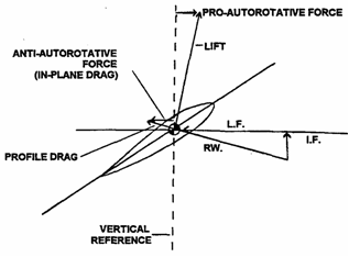
Shall be power recovery no lower than 10 Autorotative aerodynamics
 Back course localizer procedures
See reverse sensing BALDY-1 Departure
After takeoff, turn to 090, climb and maintain 900, 100 kias.
Intercept the NSE 135 radial and track outbound.
Intercept the 6.5 DME arc and climb to 1500.
Follow 6.5 DME arc to intercept the NSE 090 radial outbound.
Maintain 1500 until baldy
NOTE: RWY 32 departure, turn 140 until abeam approach end of 32, then 090. Base Recovery Course (BRC) and Foxtrot Corpen
Foxtrot CORPEN is the true course of the ship sort of. Its more like this: The ship is at point A, in two hours, it plans on being at point B which is some lat and long. On its way from point A to point B, it makes many turns and corrections for whatever reason. The heading during those turns and corrections, is actually the BRC or what the ship is heading at that time. The straight line heading from point A to point B is called the Foxtrot CORPEN.
BRC is the magnetic course of the ship at that time as it snakes its way from A to B. Basic instrument syllabus
Preparation is the key to professionalism. :D Battery relay light
When starter switch is turned on, the Battery Relay caution light illuminates indicating that the RCB circuit is being bypassed. Thus during a battery start, the RCB will not trip the battery power off of the busses.
The RCB will sustain a current load of 250 amps for 10 to 20 seconds at 25 ° C but will trip if constant current load exceeds 125 amps. When it trips, it can be manually reset.
Can also trip due to high ambient temps, low battery voltage, lengthy engine starts, or battery recharging. Battery system and malfunctions
BATTERY HOT 60+-3, BATT HOT caution light
Battery off, land as soon as possible
BATTERY TEMP 54+-3, BATT TEMP caution light
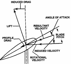
Battery off, Flight may be continued Blade element diagram
 Blowback (normal approach/transition to forward flight)
Pitch up tendency as you accel or pitch down tendency as you decal due to dissymmetry of lift that causes blade to flap and generate extra lift on the advancing blade. Boost-off approach
1. ON THE DOWNWIND LEG THE INSTRUCTOR WILL TURN THE HYDRAULIC SWITCH OFF TO SIMULATE HYDRAULIC SYSTEM FAILRE
2. FLY A PATTERN AT A COMFORTABLE AIRSPEED FOLLOWING THE PROCEDURES SIMILAR TO THE NORMAL APPROACH. DO NOT SLOW TO A HOVER BUT TERMINATE IN A FIVE FOOT AIR TAXI AT 5KTS.
3. WHEN STABILIZED IN AN AIR TAXI, INSTRUCTOR WILL ASSUME CONTROL OF THE A/C AND THE STUDENT WILL TURN THE BOOST BACK ON WHEN REQUESTED. Brevity Codes
BR Breakup and rendezvous
CO Crossover
CT Cruise turns
CD Climbs and descents
LD Lead change
TL Takeoffs and landings
BO Breaking off
OR Overrun
HS High speed approach
PTR Proceed to route
RTB Return to base
CC Combat cruise
PF Parade formation CAT II/III ILS
CAT I
Decision Height (DH) 200 feet and Runway Visual Range (RVR) 2,400 feet (with touchdown zone and centerline lighting, RVR 1800 feet).
CAT II
Decision Height (DH) 100 feet and Runway Visual Range (RVR) 1,200 feet
CAT IIIa
No DH or DH below 100 feet and RVR not less than 700 feet
CAT IIIb
No DH or DH below 50 feet and RVR less than 700 feet but not less than 150 feet
CAT IIIc
No DH and no RVR limitation. CAUTION SYSTEM
Alerts the pilot to a system fault.
Powered by DC common bus, protected by caution light C/B
Has a bright/dim switch next to AntiIce for all amber lights, AFCS, GPS, Clear Chip
Has a test switch that will cause illumination of all worded segments.
Chip detectors are installed on the drain plugs of the trans sump, engine sump, and tail rotor gearbox.
Fire warning system has warning light, fire det test switch, fire det control box, heat sens fire element located on the upper portion of the interior engine cowling.
Engine out sensor splined to the Ng tach drive shaft causing engine out audio unit to emit beep and activate eng out warning light when Ng drops below 55+-3%
Overtemp light attached to TOT gauge and illuminates when 810-927C for 10s or >927C
Rotor RPM Warn System splined to Nr tach gen and activates tone and ROTOR LOW RPM when Nr drops below 90+-3%
Audio Mute Switch controls the tone of engine out and low rotor rpm horns to headset.
Note: The ENG OUT and ROTOR LOW RPM warning light circuits are deactivated by pulling the CAUTION LT C/B
Warning: During daylight ops with the DIM mode on amber colored lights hard to see
Caution: CLEAR CHIP light illuminates during cont test dont push button
Note: Collective cutoff switch disables low rotor rpm audio unit when collective down
Caution: The audio mute switch should be left in the audio position during flight.
LIGHTS:
Hydraulic pressure: when pressure drops below 300psi
Duct High Temp: Excessive heat in ducting. (Land as soon as practical)
Eng Fire: Excessive heat in engine compartment.
Main Gen/Gen Fail: Main Generated has failed
SPARE
light incorrectly wired, check other ind. Land as soon as possible"
SPARE
light incorrectly wired, check other ind. Land as soon as possible"
Fuel Low: Less than 20 gal. land with min of 10gal (Land as soon as possible)
TOT:
once per sec in trans. Twice per sec when exceed (Land asap)
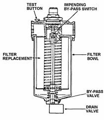
A/F Fuel Filter Impending bypass of the A/F fuel filter (Land as soon as possible)
Fuel Pump: One or both fuel boost pumps inop.
TRQ:
once per sec in trans. Twice per sec when exceed (Land asap)
T/R Chip Metal part. on tail rotor gear box chip det. (Land asap)
Eng Chip (Clear chip) Metal part. on engine det. If secondaries: Land asap
If not: Clear chip, if light goes out continue, if not, land asap
If second chip within 30 min of first: land asap. If out of 30, repeat
If third chip: Land asap
Trans Oil Chip Metal part. on Xmissn chip det. (Land as soon as possible)
Battery HOT Battery case temp is 60+-3C or higher. Bat off, Land asap
Battery Temp Battery case temp is 54+-3C or higher. Bat off, continue flight
Trans Oil Press Xmission oil press below 30+-2psi Land as soon as possible
Trans Oil Temp Xmission oil temp at or above 110C Land as soon as possible
Eng Out Ng at 55+-3%, + audio signal. Monitor Nr auto or land asapract.
Rotor Low RPM Nr less than 90%. ENG FAIL or if just tach, land asapract. CHARLIE and DELTA patterns
Charlie Pattern:
Normal landing pattern? Not sure, will update when I find out.
Delta Pattern:
VFR holding pattern in the vicinity of the ship. (just like when we used to go the Delta pattern in the T-34s when those civilian bubbas would come in for landings)
The overhead DELTA is a left-hand racetrack pattern around the ship at 500 feet MSL, oriented on the ships heading and flown at optimum airspeed
The port/starboard DELTA pattern is a left / right racetrack pattern at the altitude assigned. Downwind turn will be commenced at the amidships position. Chart Preparation for night navigation
Important to perform a complete map study prior to attempting low level navigaton.
Go over route mentally and attempt to visualize flight path realizing what you wont be able to see, what you might be able to see, and what you should definitely be able to see. COLD WEATHER LIMITATIONS
Pilot must be more thorough in preflight at or below 0 deg
Fuel and servicing should be accomplished immediately after engine shutdown to prevent condensation
All vents and openings must be checked for ice
Takeoff is prohibited with snow or ice on helicopter due to CG shifts
Flight controls may be difficult to move after helo has been cold soaked
Have affected controls thawed by preheating.
APU should be used to ensure smooth start.
Sudden loss of oil pressure could be caused by broken oil line
Intentional flight into icing conditions is prohibited. Combat cruise, section low-level flight/navigation
Combat cruise is designed to allow maximum flexibility and maneuverability while retaining control and flight discipline. It allows Wing to fly anywhere on an arc from 10° forward of abeam on the left to 10° forward of abeam on the right. The optimum position is on the 45° bearing with 4-5 rotor diameters of lateral separation and level with Lead. When Lead initiates a turn, Wing will maintain longitudinal clearance on Lead utilizing radius of turn. (To decrease distance, increase bank; to increase distance, decrease bank.) As soon as Lead rolls level, positions will be resumed with Wing balancing the formation. Prolonged flight in the area within 30° of the tail (blind spot) should be avoided. Compass locator
When Compass locator is part of the ILS installation (NDB), RMI works for ADF orientation, intercepts, holding, etc. COMPRESSOR STALL
INDICATIONS:
popping or rumbling noise, vibrations, rapid rise in TOT, Ng fluc.
WARNING: be prepared for complete power loss.
PROCEDURES:
*COLLECTIVE REDUCE (maintain Nr within limts)
NOTE: slight power reduction will often eliminate compressor stalls
*REDUCE SEVERITY OF MANEUVER
if TOT is within limits:
*LAND AS SOON AS POSSIBLE
if TOT not within limits:
*TWIST GRIP REDUCE to maintain TOT within limits.
*CHECK POWER AVAILABLE with Nr in limits.
if power is not sufficient:
*AUTOROTATE
if power is sufficient:
*LAND AS SOON AS POSSIBLE
WARNING: when accel engine during engagement exceeding 40% may induce it
NOTE: mild compressor stalls may occur that will allow powerd flight if TOT ok Cone of confusion
Is about 100 degrees wide for TACAN (40 to 50 degrees for VOR) therefore no TACAN holding at station, but at a point away from station, and use MIN DME for station passage. Confined Area Takeoffs and Landings (CALs)
1) Pattern altitude of 300 to 500 AGL and 70kts. Make a reconnaissance of landing zone to ensure clear and best arrival/departure points. Descend no lower than 200 no slower than 50kts on reconnaissance pass. Account for wind and choose best arrival point. Plan flight path to place helo within auto distance of areas most favorable for forced land. When not possible to keep LZ in site, select specific reference points. Ensure sufficient power is available prior to attempting the approach.
2) When abeam, commence a descending, decelerating turn to arrive at 90 300 60kias
3) Level off at 300 continue decel to arrive on courseline with 800 to 1000 feet at 300 AGL. Report on final. Continue to decel to 45.
4) Intercept glideslope (25 to 45 °) reduce power begin descent.
5) Adjust angle of descent such that tail rotor will clear obstruction by 10 feet and touchdown will be in the upwind 1/3 of the LZ.
6) Anticipate sloping or rough terrain in the LZ, plan on coming to a hover to evaluate surface prior to touchdown (TW-5 generally stops approach at hover)
7) Dont land in a spot of Pr > Pa.
8) Select best takeoff route optimizing wind and obstacles including 10foot clear
9) Receive clearance from crewman and pilot for takeoff and call on UHF 170, lifting CAL Zone ____
10) From a hover, check gauges and caution lights, smoothly increase power to clear highest obstacle by ten feet. When able, smooth accel and trans to normal takeoff. Keep scan going and continually clear all parts of A/C
11) When clear of all immediate obstructions, maneuver to avoid other obstacles. Contact approach
Approach procedure that may be used in lieu of a standard approach. Must be requested. Allows pilot to deviate from instrument approach procedure and proceed to destination airport by visual reference. Must have 1 SM visibility. Pilot assumes responsibility for obstacle clearance. Control feedback
Feedback in the cyclic or collective is caused by high loads in control system.
Severe maneuvers can be of sufficient magnitude to overpower or feed through the main boost cylinders and into the cyclic or collective.
Pilot will feel this feedback as oscillatory shaking.
Varies with severity of the maneuver.
Regard as a clue that high control system loads are occurring and to reduce severity. Control points and checkpoints
Control point:
Easily identifiable points and provides positive control and coordination during the flight.
If photographs are available, they will aid in the recognition and indentification.
Checkpoint:
Landmark along the route used to verify aircraft position. Copter procedures
Visibility cannot be cut in half already considered in the approach mins
Scale ring is usually cut in half (5NM instead of 10NM)
Usually incorporate steeper approaches. Course receiver failure
If course deviation bar is fully deflected when inside of final approach fix and runway is not in sight, execute missed approach COURSE RULES (CHOCTAW)
From Fish proceed south along east side of Tower 438 Field to HWY 90 then to point ECHO.
Once clear of Santa Rosa, switch to Choctaw Tower (380.8)
Choctaw Tower, (call sign), 5 miles to the north, inbound
Perform landing checks and proceed to Choctaw at 900 MSL.
Descend to pattern altitude south of the Yellow river.
Departures to north shall proceed straight out from RWY 36 or from the downwind from RWY 18.
Remain at 700 MSL until intercepting course rules to Point ECHO. COURSE RULES (DUKE)
From fish, fly 130 toward HWY 90 at 900, 100KIAS
Once clear of C, switch to 389.1 (eastern common) and 124.05 (Eglin Approach)
Parallel HWY 90 remaining one mile north.
Climb to 1300 abeam Harold.
Contact Eglin Approach Eglin Approach, Navy 1E-123, Harold, inbound to Duke
Cross CEW R-180 and proceed to Point ROCK (HWY-85 and I-10)
Freq change to Duke Tower (133.2 or 290.45) and report Point ROCK inbound
Adjust to pattern altitude. Adjust to pattern airspeed just before entry.
Depart traffic pattern to the NW at 700
Join HWY 85 and follow to the Shoal River Bridge. Report Clear
Turn to 320, turn on searchlight, climb to 1300 and proceed northwest of I-10.
Contact Eglin approach and state intentions.
Continue northwest 1 mile north of 1-10 then westbound until reaching Galliver (189 and 90)
Proceed west 1 mile north of 90 until east of Harold. Switch to Santa Rosa Crash for transition and obtain ATIS.
Contact Pcola Approach for JUNIPER or HUGHES arrival. COURSE RULES (Harold OLF)
NOLF HAROLD (Field elevation, 159 feet)
1. Aircraft departing South Whiting Field for Harold NOLF shall proceed to POINT ABLE at 900 feet MSL and 100 KIAS, turn southeast, fly a course of approximately 1100. Upon reaching the intersection of Coldwater Creek and Blackwater River (POINT FISH), switch to NOLF Harold's frequency, and proceed to POINT HOTEL (intersection of power lines, dirt trail, and old pipeline, approximately 1050), and, make the radio call, ""Harold (call sign), POINT HOTEL, inbound."" Harold Crash shall respond with the course in use. Upon reaching POINT HOTEL descend to 700 feet MSL and complete the landing checklist.
2. Aircraft departing the eastern operating area for Harold NOLF shall proceed to POINT RACETRACK (1.5 miles southwest of Bryant Bridge) and report POINT RACETRACK inbound. Upon reaching POINT RACETRACK descend to 700 feet MSL, complete the landing checklist, and then follow the power lines/Hwy 90 to Harold NOLF.
3. Aircraft on the Black Route may transition to NOLF Harold via POINT HOTEL. All other route hops departing the eastern operating area for NOLF Harold shall proceed to POINT RACETRACK (remaining to the east of NOLF Harold until POINT RACETRACK). Caution: Aircraft transitioning from the Black route shall avoid the established flow of traffic at POINT JUNIPER.
4. Entry into the Harold traffic pattern shall be made by splitting the field at 700 feet MSL and 100 knots on a heading parallel to the landing course, simultaneously begin a level speed change to pattern airspeed (70 KIAS) and call splitting Harold for the left or right pattern. At the upwind field boundary, turn left or right to join the desired pattern and descend to pattern altitude.
General
1. The courses at Harold are 09, 18, 27, and 36.
2. The crash crew is located on the east side of the field. The course indicator is located adjacent to the crash crew.
3. Aircraft approaching the site for entry must stay clear of the traffic patterns. Do not cross the departure point during entry.
4. A maximum of seven aircraft may operate at Harold at one time. When confined area operations are being conducted, that pattern shall contain a maximum of two aircraft. With two aircraft operating in the confined area landing / external load pattern, both aircraft must be performing these maneuvers or depart the pattern.
5. The only maneuvers that may be performed to a touchdown are the vertical landing or no-hover landing.
6. When the pattern is full, only FORM solo's are allowed to split and land to wait for the pattern to open up.
7. Simulated engine failures or simulated emergencies are not permitted while splitting.
8. Tactical operations have priority. Normal operations may be flown.
Confined Area/External Load Pattern
1. The confined area/external load pattern shall be contained in the northern half of the site when on a course of 09 or 27. When the course is 18 or 36, the pattern will be contained in the western half of the site.
2. Aircraft practicing external load operations must remain within the field boundary to prevent damage to civilian property. The external load shall not cross into the normal pattern side of the field, overfly other aircraft or the crash crew. The external load blocks shall be stowed adjacent to the pinnacle.
3. If only one aircraft is operating at Harold, the confined area landing zones may not be utilized until the crash crew can be repositioned to the confined area section of the field.
Departures from Harold shall be made from the northeast corner. Aircraft must be at 700 feet MSL in the pattern containing the northeast departure point in order to depart. Upon departure accelerate to 100 knots and proceed to the appropriate channel entry point or working area. COURSE RULES (SANTA ROSA)
Button 1: Get ATIS
Button 2: South Whiting Clearance Delivery, Factoryhand ___, request clearance, VFR to Santa Rosa, 4+00, 2 souls
Button 3: South Whiting Ground, Factoryhand ___, taxi with clearance, VFR to Santa Rosa, from ____, with information ___
Switch to tower at the 2 board (Spot 4) or when clear of the flight line. (Spot 1 or 2)
Button 4: South Whiting Tower, Factoryhand ___, number 1 holding short/approaching spot 4/1 or 2, ABLE departure."
Fly to point ABLE 900feet, 100kts."
At point ABLE (Water tower 3/4mile southeast of the field):
Pensacola Departure: Pensacola Departure, Factoryhand ___, 900."
Turn to approx 110 and head direct to Point FISH.
At point FISH (Intersection of ColdWater Creek and BlackWater River):
Fly a course to remain east of Tower 438 field.
At Tower 438 field:
Pensacola Departure: Pensacola Departure, Factoryhand ___, Antenna 438, clear."
Squawk 4677
Contact Santa Rosa Crash on button 9: Santa Rosa Crash, Factoryhand ___, inbound from the north"
Crossing HWY 90:
Descend to 700 MSL and complete the landing checklist.
Split the field, Patterns are at 500 AGL and 70kts."
Depart Santa Rosa from the northwest corner of the field.
Join course rules at 100 kts and proper channel alt. (900 for now)
Report to Crash: Santa Rosa Crash, Factoryhand ___, departing.
Obtain ATIS and contact Pensacola Approach: Pensacola Approach, Factoryhand ___, off Santa Rosa, request Hughes arrival, with information __.
At intersection of I-10 and 87: follow I-10 towards point ECHO
At point ECHO (intersection of I-10 and 89): proceed at 900 on a course of approx 300 direct to point HUGHES.
At point HUGHES (intersection of 87 and 90): If radar identified, auto switch to tower (button 4): South Whiting Tower, Factoryhand ___, Point HUGHES. Follow 87 to Point IGOR.
At point IGOR (intersection of 87, 89, powerlines): proceed inbound at 700 MSL, perform the landing checklist, and enter the traffic pattern maintaining 100 kts until just prior to pattern entry. South Whiting Tower, Factoryhand ___, Point IGOR for Spot __. Crew comfort levels
Basically, you are low to the ground this is mostly talking about the training time out policy. If you arent comfortable, let your IP know hell probably laugh at you, but your safety is still very important to your IP. Also, if you dont read well in cars without getting sick youll probably love looking at a chart as trees zoom by at 90 kts. SO, carry some sick sacks if you are weak! Crew coordination: during emergencies
Stuff we brief in the Natops brief (system, aircraft emergencies) Crew coordination: Instrument approach responsibilities PNAC
Read Missed Approach instructions
Copy down clearances/instructions
Read out MDA/DH/Step Down Altitudes
Look for runway/take over when runway in sight after stating such and remaining visual. Crew coordination: integration of aircrew
Crew members other than the pilot and copilot are assigned to fly on almost all fleet aircraft, performing a variety of mission-unique tasks.
As highly skilled individuals, they contribute to the successful completion of your mission.
They assist in terrain recognition and observe for clearance of obstacles during hovering and landing.
During external load operations and confined area landings, the crewman is the pilot's primary means of observing and relaying vital information external to the aircraft.
He is your "eyes" in the back!
The crewman is responsible to the pilot for preflight briefings and procedures specific to external load operations and confined area landings Criteria for continuing an instrument approach to landing
Pilots shall not descend below the prescribed minimum descent altitude (MDA) or continue an approach below the decision height (DH) unless they have the runway environment in sight and in their judgment a safe landing can be executed.
Runway Environment:
1. Approach lighting system (lets you come down to 100 feet above TD zone, lower if you have red terminating bars or red side row bars in site)
2. Threshold, Threshold markings, or Threshold lights.
3. Touchdown Zone, Touchdown Zone markings, or Touchdown Zone lights.
4. Runway, Runway markings, Runway Marking lights.
5. REIL (Runway End Identifier Lights)
6. VASI (Visual Approach Slope Indictor) CRM
You should be experts at this now!!! PSSST, the GPS is your second Co-Pilot!!! Let him do most of the work. Know how to use the DT page gives you your projected time at all your points helpful for those PTAPTP reports. CRM and interaircraft communication
Lead PAC performs area check-in for formation
Wingman PAC initiates all maneuvers
Lead PAC rogers all maneuvers
Lead PNAC ensures safe navigation for the flight
Wing PAC ensures proper separation from Lead.
FREQ CHANGES:
There are two basic ways to accomplish a frequency change. These are:
1) Positive Control. This method ensures the flight leader that each aircrew member hears and acknowledges all calls and frequency switches.
Example:
Lead: "(Aircraft call sign) Check in UHF."
Flight: "Two","Three","Four"
Lead: "(Aircraft call sign) switch button 3
Flight: "Two,""Three,""Four"
Lead: "South Ground, (aircraft call sign) . . . departure call."
2) Automatic Switch. This method depends on each aircrew member taking detailed notes in the brief and listening intently on the radios. During frequency changes and the passing of information, the flight leader assumes that each aircraft is up the correct frequency and is listening.
Example:
Lead: "Ground, (Aircraft call sign), taxi"
Ground: "Roger, (Aircraft call sign), you're cleared to taxi."
Lead: "(Aircraft call sign), Roger"
(All aircraft switch to tower frequency at pre-briefed time/location)
Lead: "Tower, (Aircraft call sign) takeoff" CRM (adaptabilty/flexibility)
The ability to alter a course of action to meet situational demands. CRM (assertiveness)
The willingness to actively participate and ability to state and maintain your position. CRM (as it relates to low level navigation)
PAC: Control the helicopter and avoid obstacles.
Keep vision outside and avoid distractions.
Report terrain and landmark info to assist in navigation
PNAC: accurate navigation
Remain oriented, monitor instruments, and perform assigned duties. CRM (communication)
Ability to clearly and accurately send and acknowledge information, instructions, or commands; and provide useful feedback. CRM (decision making)
Ability to use logical and sound judgment based on the information available. CRM (leadership)
The ability to direct and coordinate the activities of other crew members, and to stimulate the crew to work together as a team. CRM (mission analysis)
Ability to coordinate, allocate, and monitor crew and aircraft resources. CRM (Night Flying)
Specific crew duties are designated to ensure the teamwork necessary to conduct night flight.
Ensure crew duties are designated during the preflight briefing and understood by all. CRM (situational awareness)
The ability to alter a course of action to meet situational demands Cruise position, cruise maneuvers and brevity codes
Cruise position
About:
Primarily used when en-route when maneuverability and navigation by all aircraft are the primary considerations.
Wing maintains position through radius of turn with minimal power adjustments.
This allows Wing to approximately match Leads fuel consumption, enabling both aircraft to arrive at the operating area with enough fuel.
For training purposes it shall be flown at 80KIAS when maneuvering and 100KIAS when transiting to and from area.
Description:
30 ° bearing with 10ft step up at 3 rotor diameters distance.
Near skid heel with far skid toe
Rotor hub just below horizon
100 of separation when you can just read the BuNo
Responsibilities:
Lead: provide a stable platform; power setting remain as near as constant
Lead: ensure flight is clear at all times
Wing: remain in position and respond quickly to avoid large power applications.
Cruise maneuvers:
Section Takeoff:
About:
Power available, wind direction and velocity, and terrain features should all be considered in determining positioning for takeoff.
Description:
South Whiting Clearance Delivery, Factoryhand 123, flight of two, wingmans side number 321, request clearance, VFR to the east, 2+00 hours, 2 souls each aircraft.
South Whiting Ground, Factoryhand 123 and flight, taxi with clearance from spots Alpha 3 and Charlie 12, with information Echo.
South Whiting Tower, Factoryhand 123 and flight, number 1 holding short spot 1 for Able departure.
Know where each other are on parking ramp.
After join up, taxi in trail to hold short
Lead obtains clearance for takeoff from tower and positions on runway centerline.
Wing follows Lead onto runway and assumes cruise position on upwind side.
Clearing turn: each aircraft turns 45 ° into each other. Inboard pilots clear outside while outboard pilots clear inside (gauges etc)
Ready signal is given (thumbs up and searchlight on)
Lead commences normal transition to forward flight.
Wing maintains cruise throughout takeoff and must be there before maneuvers.
Responsibilities:
Lead PAC makes all radio calls for formation.
Lead PNAC/Wing PNAC gives signal.
Crossover: CO: Charlie Oscar
About:
Teaches wing control of relative motion while safely maneuvering about Lead.
In a tactical situation, wing crosses at will. In training, will be announced.
Description:
Wing shall increase step up to 20 (far skid toe touching bottom of fuselage)
Start slide to cross Leads tail. (Upper anti-coll light through main tranny)
Reduce power, realign heading, stabilize, drop down to new position.
Responsibilities:
Lead: clears the flight and maintains constant heading, alt, and A/S
Wing: calls for maneuver.
Cruise Turns: CT: Charlie Tango
About:
Radius of turn maneuver enabling the pilot to practice maintaining cruise position while in a turn without adjusting power.
Airspeed of approximately 80KIAS and 1000AGL with 10 or 20 ° AOB
Lead smoothly rolls to the desired angle of bank in either direction.
Initial airspeed may dissipate during the turn to a minimum of 60KIAS
Lead continues for a series of turns and reversals in the opposite direction.
Description:
Lead initially turns using 10 ° AOB for 180 °.
Lead then reverses turn in the opposite direction and uses 20 ° AOB until wing calls for reversal.
Wing shall attempt to stay in cruise position relying on radius of turn and constant power. To increase distance less AOB, To decrease distance more AOB.
Wing shall do this by sliding to outside of turn on 30 ° bearing line. As distance starts to increase, slide back to inside of turn on 30 ° bearing line. As distance starts to decrease, slide back to outside of turn. RINSE AND REPEAT.
Responsibilities:
Lead: clears the flight and maintain altitude, power setting and angle of bank.
Wing: calls for maneuver.
Cruise Climbs and Descents: CD: Charlie Delta
About:
Enable formation flight to climb and descend together in flight.
Climb or Descend at a power setting which yields 500 fpm and 80KIAS
Description:
Lead smoothly adjusts power for a climb/descent rate of 500fpm and 80kts and rolls into a shallow turn (10 to 15 ° AOB).
Lead should reverse turn at least once during climb and descent.
Climb or Descend for at least 500 of altitude change, after which Lead will stabilize momentarily, then transition to a climb or descent back to starting altitude.
Wing remains in cruise position during the climb and descent. Wing should attempt to climb on the inside and descend on the outside of lead.
Responsibilities:
Lead: clears the flight.
Wing: calls for maneuver.
Breakup and Rendezvous: BR: Bravo Romeo
About:
Running rendezvous and carrier rendezvous. We do carrier rendezvous.
Rendezvous gives aircraft the ability to join after takeoff.
Done from cruise formation on a cardinal heading.
Description:
Lead shall break away from Wing using 30 ° AOB.
Maintain this AOB, altitude, and airspeed for 180 ° of turn.
Wing breaks in the same direction of turn after Lead passes through a 45 ° bearing line oriented from Wings nose.
Once all aircraft have completed the level 180 ° turn, the formation will be in an extended trail position of about 800 to 1000 feet of separation.
Wing shall keep Lead on the horizon.
When established in position and ready to commence rendezvous, Wing shall state the flights call sign and key the UHF twice.
Leads turn may be in either direction. (be aware of suns location)
Lead will flash to 20 ° AOB momentarily then stabilize at 10 ° AOB for 180 ° of turn while maintaining altitude ant 80KIAS.
Wing turns inside Leads radius of turn to effect join-up.
Establish on Leads 45 ° bearing using AOB keeping Lead on the horizon.
Slide back to 30 ° bearing line at three-rotor diameters and establish in cruise position inside the turn.
Responsibilities:
Lead: clears the flight.
Wing: calls for the maneuver.
Overrun: OR: Oscar Romeo
About:
Enables formation to maneuver to a safe position when a dangerous closure rate is recognized during turns or join-up. Allows Wing to clear Lead.
Description:
Wing increases step-up to 20 and levels the wing enabling Wing to slide to outside of Leads turn.
Wing may regain cruise after safe separation from Lead is attained keeping Lead in sight at all times.
After Wing has completed maneuver, Wing shall announce, Oscar Romeo on UHF.
Responsibilities:
Wing: must recognize closure rate and not hesitate to initiate an overrun.
Lead Change: LD: Lima Delta
About:
Enables the flight to exchange Lead.
All lead changes shall be accomplished with positive two-way radio comms (except as briefed in lost comms section)
Executed from level flight cruise position at 80KIAS.
Pilots on the inboard side of section shall be at the controls.
Description:
Wing shall increase lateral separation, move abeam original Lead and transmit, (Aircraft call sign) in position for lead change.
When both pilots in visual contact, original Lead will transmit, (Aircraft call sign), you have the lead.
Original Wing replies, Roger, (Aircraft call sign) has the Lead.
From this point the original Lead becomes Wing and shall effect a slow drift aft to the 30 ° bearing line while maintaining lateral separation.
The original Wing is now Lead and maintains constant heading, altitude, and airspeed.
On deck is the same procedures: original Wing takes safe lateral separation, taxies abeam Lead, makes same radio calls as before, but then continues to taxi far enough ahead to place Wing on the 30 ° bearing line.
Responsibilities:
Lead: clear the flight and maintain constant airspeed and altitude.
Wing: call for maneuver.
Section Landings:
About:
Enables formation flight to land in formation
Pattern alt and A/S of 500ft AGL and 70KIAS with Wing in cruise position terminating in a hover followed by a vertical landing.
Description:
Lead shall use normal approach procedures to allow sufficient straightaway and shallow glideslope so that Wing need not make rapid power or nose attitude changes.
Wing makes expedition power and attitude adjustments to maintain solid cruise position until reaching short final.
Wing will use procedures used during CD and CT to maintain position and plan to land on the upwind side of Lead.
At 100 on short final, Wing will divide scan evenly between Lead and landing lane controlling the closure rate to the landing zone.
Responsibilities:
Lead: use normal approach procedures to allow sufficient straightaway and shallow glideslope.
Wing: make expedition power and attitude adjustments to maintain position. Dark adaptation
When fully night adapted, the eyes become extremely sensitive to light.
Exposure to a light source will cause partial or complete loss of night vision.
Caution must be taken to avoid exposure to light sources inside and outside of aircraft. DD-175 & DD-175-1
Signing of Flight Plan
Flight is authorized
Adequate/Accurate flight planning done
Fuel and Wx requirements met
Each pilot in form flight has req'd Wx brief
PIC has instrument rating if any of flight to be IMC
Passengers briefed and manifested
Weight and Balance completed
PIC acknowledges responsibility for safe and orderly conduct of flight Deck spotting
Dont focus on the deck too long. Its pitching and rolling and might jack you up. Keep your scan moving so that you get a good idea of what is going on and dont trap yourself into getting disoriented by staring at a moving deck.
Also can be the location of aircraft on spots on vessels that have multiple landing spots. Departure Procedures
RWOP CHAPTER 5
DIF ON EARLY AND LATE 57B
OLD / NEW
Cargo Hook: NO / YES
Fuel Capacity: 76 Gal / 91 Gal
Refueling Type: Gravity / Gravity and Pressure (<125PSI)
ECS: High Press Water Sys Uses Bleed Air 70HP / Freon system that uses only 5 HP
Duct High Temp: NO / YES Disorientation procedures
Climb before you make it worse, find a major point that you can find on your chart to reorient your self. Dissymmetry of lift
In forward flight, retreating blade sees less velocity.
Hence flapping: advancing blade sees more lift, and flaps upward. DITCHING
POWER ON:
PASSANGERS AND CREW ALERT
SHOLDER HARNESS LOCK
MAYDAY/IFF TRANSMIT/EMERGENCY
PERFORM NORMAL APPROACH TO HOVER 3 TO 5 FEET
DOORS JETTISON
NONESSENTIAL PERSONEL EXECUTE EMERGENCY EGRESS
HELECOPTER MOVE, SAFE DISTANCE AWAY
VERTICAL LANDING PERFORM
TWIST GRIP CLOSE
COLLECTIVE INCREASE SLOWLY TO MAX PITCH
CYCLIC MAINTAIN HELO UPRIGHT ALAP
EMERGENCY EGRESS EXECUTE
LIFEVEST INFLATE (WHEN WELL CLEAR)
POWER OFF:
*AUTOROTATE
*SHOLDER HARNESS LOCK
*CREW/PX ALERT
*SQUAWK EMERGENCY
*DOORS JETTISON
WARNING: DO NOT EGRESS UNTIL WELL CLEAR OF HELO
*UNDERWATER EGRESS EXECUTE DOT COM'S 2 cents on HTACs
DUE TO THE NAVYS INFINITE WISDOM, THE CAT II FTI HAS NUTHIN ON THESE HTAC FLIGHTS (and the mitac class was awesome not) SO, THE HTAC NOTES I HAVE ARE MOSTLY FROM HAND ME DOWN SOURCES AND COMMON SENSE."
DOT COMs 2 cents on RI Simulator Check Ride (RI-09X)
The instructor usually tells you what you are gonna do during the brief and gives you a few minutes to look at the approaches. Some dont, some get you in the sim and tell you when you are strapping in, or they tell you that you are at XXX airport and the Wx is XXXXXX and they let you request what you want. First hop we shot the ILS 17 to PNS, followed by the VOR 8 to PNS followed by the NDB 35 to PNS followed by the PAR at NIP. Shot the ILS 17 normal, then missed approach, and shot the VOR 8. The WX mins for VOR 8 are higher than for ILS 17 and we didnt have the mins to shoot the VOR. Requested updated weather and now had the mins to shoot it. Dont forget to get updated weather to make sure you are still good to go. Went missed approach and requested radar vectors to final for the NDB 35. Went missed approach and as we were climbing out got an A/F fuel filter light. Declared an emergency and requested the PAR to NIP with expeditious vectoring so the controller knew not to take us out to BFE! While on final for the PAR, fuel control unit failure. Controlled the A/C till we broke out, lost engine, auto."
Second hop we shot the CEW VOR A followed by the CEW NDB 17 followed by the PAR at NDZ followed by ILS 17 to PNS. We shot the CEW VOR A and we had the GPS VOR A loaded in and sure enough, on procedure turn inbound, the VOR died and we took over on the GPS VOR A. Went missed approach and requested the NDB 17. Had the GPS 17 backing it up too so the instructor killed our GPS. Shot the NDB 17 no probs. Went missed approach and requested the PAR to NDZ. During the PAR to NDZ, experienced fluctuating Nr. Since we had no secondaries it was a land as soon as practicable so we didnt declare emergency but told the ground controller it would be full stop. Of course, we didnt break out so informed approach of our situation and they suggested weather might be better at PNS so hence the ILS to runway 17 at PNS. We got radar vectors to final, and during the radar vectors to final we got a Trans Press light. Now land as soon as possible so we declared emergency and requested expeditious vectors again and he said he could turn us early on to final. We took it, as we turned onto final, we got a transmission chip light (Nr tach, tranny oil, tranny chip HMMMMM) and the aircraft started bouncing around. Decided we needed to get down, and asked approach the lowest they could get us while vectoring. The ILS 17 is at 1700 feet and they were able to allow us down to 1500 while vectoring. When we intercepted final, we turned it into a localizer so we could jump down to our MDA (600 feet) in the hopes we would break out. If we didnt, we planned on trucking in bound, reintercepting the glideslope and continuing with the ILS. We broke out around 700, saw the field, but took it to the grass below cuz it was land ASAP. Dont let those rabbit lights sucker you into going all the way to the field after youve broken out. LAND ASAP means take the field below you!! Got to about 30 feet, Tranny seized and we fell like a brick. :D "
These are the types of scenarios youll get. Remember to back up all your stuff with other approaches. DONT FORGET TO START TIMING in case you loose the glideslope on an ILS or the DME on a VORDME or TACAN. PLAN on loosing your RMI for failed card stuff. We didnt but I hear most do. PLAN on getting a MAJOR EP on your last approach, and maybe a MINOR EP (land as soon as practical type ep) on your second to last approach. Usually the minor EP you get on the 3rd approach will lead into your biggie on the last one. IE Tach Gen fluct -> Tranny oil problems etc. Its a little different than the first 8 hops in that you are shooting multiple approaches AT MULTIPLE AIRPORTS which means constant flipping of your approach plates to dif pages, multiple approach briefs, etc. So youll pass controls quite a bit. Its a good hop shows you what itll be like when we are doing multiple approaches to multiple fields on later RIs. Fun stuff. Its nothing you hadnt done in earlier RI sims, just all jammed into one flight. GOOOOOD TIMES!!!!"
Duct high temp caution light
Heater Malfunction
INDICATIONS:
DUCT TEMP HIGH caution light illuminated.
PROCEDURES:
1. CABIN HEAT valve -OFF.
2. AIR COND/FAN switch -FAN.
3. HI/FAN/LO switch - HI.
If light extinguishes:
4. Continue flight.
If light does not extinguish:
5. Land as soon as practicable. DYNAMIC ROLLOVER
Accelerated roll about a ground attached point peculiar to primarily skid configured helicopters. Helicopter gets in a situation where it is pivoting around a skid. If bank angle builds past 15, the helicopter will enter a rolling maneuver that cannot be corrected with full cyclic.
The critical rollover angle is even worse for a right skid down condition, crosswinds, lateral center of gravity offset, and left rudder pedal inputs.
Care must be taken to keep aircraft trimmed, especially laterally. Critical recovery angle may be exceeded in less than 2 seconds.
Collective is much more effective in controlling the rolling motion because it reduces main rotor thrust. Smooth moderate reduction of less than 40% is adequate to stop the rolling motion with about 2deg bank angle overshoot.
The only restoring moment capability is the weight of the helicopter times the offset distance. This goes to zero at approx 31 degrees.
With full lateral control deflection, mast bumping occurs when roll rate reaches 10 degrees per second.
TO AVOID ENTERING ROLL PILOT SHOULD
Maintain trim
Not allow aircraft roll rates to become large
Not allow aircraft bank angle to become large
Fly smoothly
DURING SLOPE LANDINGS
Descend slowly placing upslope skid down first
Lateral cyclic into slope to maintain level TPP
Set cyclic to neutral position once assured helo will remain stable
Do not land on a slope greater than 7.5 degrees
If helo rolls upslope side (5 to 8 degrees) collective down. ECS system/malfunctions
The environmental control system consists of a vapor cycle air-conditioner for cabin cooling, and cabin heating provided by engine bleed air, The environmental control system incorporates an environmental control panel and a cabin heat valve.
The air-conditioner system consists of an enginedriven compressor, a condenser, and an evaporator, both using electric motor-driven blowers. AIR COND or FAN may be selected. In the AIR COND mode, the evaporator blower is automatically activated, distributing cold air. The FAN mode permits cabin air circulation only, either in a HI or LO blower speed as selected by the second switch. Temperature control is accomplished through a rheostat to set desired cooling air temperature.
The cabin heat valve is a single (INC/DECR) rheostat knob that allows warm air to flow from the cabin heater to the cockpit. When the cabin heat valve is on, the environmental control panel should be set to FAN/HI for maximum effectiveness.
Malfunctions:
An ECS malfunction is normally indicated by a medium-frequency vibration accompanied by a rumbling or grinding noise from the engine compartment. It is caused by a compressor malfunction or improper belt tension.
PROCEDURES:
1. AIR COND/FAN switch -OFF.
2. Land as soon as practicable. Effects of adverse weather on mission planning
Ceiling and visibility are the two aspects of adverse weather that most affect us.
However, the can be assets cuz they reduce detection in a threat environment.
Visibility is the primary limiting factor.
Will determine if a flight can be conducted
Adequate visibility required for takeoff, enroute, and in area.
During flight, must maintain visual reference with the ground to avoid obstacles.
If vis is reduced, A/S may be decreased to provide added response time. Electrical system/malfunctions
Generator Failure
WARNING: with bat gone, both fuel boost pumps are inop. BELOW 6000 LASAP
WARNING: with one or both boost pumps inop fuel quantity below 20 unusable
NOTE: prior to shutting of all elect power, pilot should determine what is essential
NOTE: in the C, time of operation of ESS No. 2 is 40 min with pitot off, 35 with pitot on
NOTE: With normal/recover switch in normal, fail of main gen will illum fuel pump lite
NOTE: Resetting bus/tie relay CB will cause main bat to power the nonessential bus.
GEN FIELD and GEN RESET C/B IN
MAIN GEN SWITCH
RESET, then ON
if power not restored:
MAIN GEN SWITCH OFF
UNNECESSARY ELECT EQUIP OFF
C NORMAL/RECOVER switch Recover as Desired
DESCEND BELOW 6000
LAND AS SOON AS PRACTICABLE
if power is restored:
CONTINUE FLIGHT
NOTE: be prepared for possible elec fire due to excessive wire load or gen meltd
NOTE: in the C, with a loss of main battery after gen fail, HSI and RMI inop for TACAN, LOC and VOR. RMIs will still provide ADF bearing. STAY VMC
Standby Generator Failure
STBY GEN C/B IN
STBY GEN Switch OFF, Then ON
if power not restored:
Land as soon as practicable
if power restored:
Continue flight.
Inverter Failure
NOTE: FORCE TRIM will function
If FCS inverter voltage is less than 111 volts:
FCS C/B (ESS-1, lower panel) PULL
Establish VMC.
Avionics Inverter Failure
AVIONICS INVERTER C/B (ESS-2, upper panel)PULL
NOTE: further flight in IMC is possible, but must be done without RMIs and yaw servo.
DC Loadmeter and voltmeter
GENERATOR CYCLE
If the problem is corrected:
Continue flight
If the problem is not corrected:
Use generator failure procedures
CAUTION: Sustained loadmeter indications greater than 70 may be caused by elec fire. ELVA approaches (Emergency Low Vis Approach)
1. Conducted to an air capable ship which as weather below approach mins. Considered an emergency procedure. Only used when inadequate fuel to bingo to GCA/CCA equipped airfield or aviation ship.
2. Skill of controller, accuracy of information displayed to controller, pilots flight proficiency are primary factors affect quality of an ELVA.
3. Gunfire control system provides most accurate real time tracking and use used on most ELVAs
4. Required radio transmission from controller are based on helo range from ship.
5. Initial approach pattern must be executed so that aircraft reaches four mile gate position at 400 and 70kts.
6. Final approach will commence at 400 and 70. Final controller must have approach plotted and have radar control of A/C prior to four-mile gate
7. For standard approaches, final approach course will be the ships BRC minus the flight deck approach angle.
8. Heading corrections on final should not be more than 5 °, if possible using half standard rate turns.
9. For missed approach, A/C will make 30 ° turn to left (right for port approach) and climb 400 feet and be vectored back into the ELVA pattern.
10. If equipment malfunctions, or limitations preclude ELVA procedures, an emergency approach or ditching may be considered.
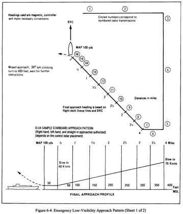 Emergency at low altitude
Step 1: SCREAM!!!
Seriously the biggest thing with this is being situationally aware of where you are at all times. Here in Lower Alabama, there are MILLIONS of farmer bob fields that you can put your busted up Charlie into if you need to. Situational awareness is key!! Emergency descent
COLLECTIVE Reduce (to minimum pitch)
Airspeed 130 KIAS (122 KIAS Max with AFCS On).
NOTE: During recovery, Nr may tend to overspeed. EMERGENCY ENGINE SHUTDOWN
Any emergency that necessitates rapid crew egress.
*TWIST GRIP OFF
*FUEL VALVE OFF
*BAT SWITCH OFF Emergency procedures/Landing site evaluation at night
Every attempt should be made to become familiar with the terrain over which night flights are made. If an emergency landing is necessary, use the landing light to observe obstructions and select a landing area. En route emergency divert fields
Under IMC, a pilot should always look for suitable landing fields in the event of an emergency. Factors which determine field suitability include approach availability, lighting (if at night), runway length, and availability of maintenance services (depending on the urgency of the situation). The IFR en route chart depicts those aerodromes with a DOD published instrument approach. To further determine whether the approaches are compatible with your navaids you should be aware of the suitable fields which lie along your intended route of flight. If an emergency occurs, after taking the immediate action prescribed by NATOPS, you will contact ATC with your situation and intentions. If necessary, ATC can assist in selection of and navigation to the nearest suitable field.
Connor says: Hey, The blue fields have published military approaches, the green fields have civilian approaches, and the brown fields dont have any approaches published. (VFR only) Here is the way that it was explained to me. It all depends on the emergency. Battery hot .. turn it off and make it to a blue field. Transmission chip w/additional fluctuations in Nr indications and green field closer to you than a blue field contact your controlling agency, declare an emergency, and get them to walk you through the civilian approach to that field. Better safe on the deck with a stressed out controller than a wife and kids collecting SGLI En route/feeder routes
The normal navigational aid spacing for airways/routes below 18,000 feet MSL is 80 nautical miles and the airspace area to be protected has a total width of 8 nautical miles, 4 nautical miles each side of centerline, within 51 nautical miles of the facility. Beyond 51 nautical miles the 4.5 degree accuracy factor determines the width of the airways/routes (approximately 2 NM in total width every 13 NM).
A route depicted on Instrument Approach Procedure Charts to designate routes for aircraft to proceed from the enroute structure to the Initial Approach Fix (IAF). (See Instrument Approach Procedure) En route low altitude chart symbols
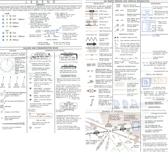 Engine chip clearing procedures
If secondaries: Land asap
If not: Clear chip, if light goes out continue, if not, land asap
If second chip within 30 min of first: land asap. If out of 30, repeat
If third chip: Land asap ENGINE FAILURE
INDICATIONS:
Nr decrease, Rapid settling, left yaw, low rotor rpm engine out lighthorn
HIGH AIRSPEED and LOW ALTITUDE
*CYCLIC IMMEDIATELY APPLY AFT
*AUTOROTATE
WARNING: rapid cyclic movement should be avoided to preclude mast bump
IN FLIGHT
*AUTOROTATE
*SHOLDER HARNESS LOC
CREW/PAX ALERT
MAYDAY TRANSMIT
SQUAWK EMERGENCY Engine failures NATOPS/FTI
NATOPS
*AUTOROTATE
*SHOLDER HARNESS LOCK
CREW/PAX ALERT
MAYDAY TRANSMIT
SQUAWK EMERGENCY
FTI
1) INSTRUCTOR WILL INITIATE MANEUVER BY ROTATING TWIST GRIP TO FLT IDLE TO SIMULATE A LOSS OF POWER.
2) LOWER COLLECTIVE TO ENTER AUTO. MAINTAIN BALANCED FLIGHT AND TRANSITION TO APPROPRIATE A/S
3) TURN TOWARD LANDING AREA, AND PLAN FOR IN THE WIND
4) MAINTAIN A/S FROM 50 TO 75 AND Nr FROM 90 TO 107%
5) PAC SHALL DIRECT PNAC TO LOCK, TALK AND SQUAWK
6) AT THE SITE:
a. TERMINATE AS A POWER RECOVERY AUTO UNLESS DIRECTED
b. IF NOT PARALLEL TO COURSELINE BY 150FT, LEVEL WINGS AND CONTINUE AUTO STRAIGHT AHEAD.
7) AWAY FROM SITE: INSTRUCTOR WILL INITATE A WAVEOFF AT OR ABOVE 300 WAVEOFF MUST BE COMPLETED BY 200 AND > 50kts Engine failures night
Procedures are still the same as day however, time required to respond will normally be longer at night due to increased psychological stress and reduced vision within cockpit. Knowing location of all controls and switches and the procedures to the emergency are critical in minimizing time delays. Engine failure with external load
Emergency Procedures
1. ICS failure:
a. Alert pilot
b. Use push/pull method on pilot's shoulder
c. Execute drop
d. Land and troubleshoot
2. Cargo hook failure
a. Advise pilot "Hold, no release."
b. Tension
c. Circuit breaker
d. Electrical release
e. Emergency 'IV, handle
f. In the event of total hook failure:
(1) Advise pilot for landing; ensure skids straddle pendant
(2) manually release pendent
3. Engine failure during pickup
a. Load, release
b. Aircraft, forward and left
c. Hookup-man, right
4. Engine failure during transition
a. Load, release
b. Execute emergency landing ENGINE OIL SYSTEM MALFUNCTIONS
On Ground:
If oil pressure is 130 to 150, do not accelerate engine until within limits
If oil pressure is greater than 150, shutdown
Airborne:
If pressure not within normal, or fluctuates: Land as soon as possible
If temperature exceeds red line: Land as soon as possible
If temperature fluctuates or falls to zero: Land as soon as practical ENGINE OVERSPEED (Nf) ROTOR RPM (Nr)
INDICATIONS:
Nr, Nf, Ng, TOT, Right Yaw, or Engine Noise increases.
PROCEDURES:
*COLLECTIVE INCREASE (to maintain Nr in op range)
*TWIST GRIP REDUCE (to maintain Nf in op range)
NOTE: Nf overspeed must be continually controlled by collective and twist grip
*COLLECTIVE/GRIP READJUST
*LAND AS SOON AS POSSIBLE ENGINE UNDERSPEEDING Nf OR Ng (LOW Nr)
If Nr can be maintained at 90% or higher, it is safe to proceed to a suitable landing site.
Sliding landing offers lowest power required.
Do not decelerate below 50KIAS while executing the power check.
INDICATIONS:
Low Nr, Low Nf
PROCEDURES:
*COLLECTIVE ADJUST TO MAINTAIN Nr IN LIMITS
*TWIST GRIP FULL OPEN
*GOV RPM FULL INCREASE
*CHECK POWER AVAILABLE WITH Nr IN LIMITS
if power is not sufficient:
*AUTOROTATE
if power is sufficient:
*LAND AS SOON AS POSSIBLE ENGINE RESTART IN FLIGHT
An engine flameout in flight most likely result from malfunction of FCU or Fuel system.
Decision to restart is pilots responsibility and dependant on experience and altitude.
Consider the cause of the failure prior to restart.
Procedures:
*AUTOROTATE
*FUEL VALVE CHECK ON
*STARTER ENGAGE
CAUTION: if Ng goes below 15%, close twist grip and perform normal start
NOTE: Ng will not decrease below minimum start speed within 10s due to ram air effect. Twist grip can be left in full open since fuel flow during the start will be on normal schedule
if light off occurs:
*LAND AS SOON AS POSSIBLE
CAUTION: Do not attempt to start above 12000 feet as TOT too fast to control Engine system
Allison 250C-20J series turboshaft engine. 420 SHP derated to 317 SHP
1) Compressor (6 stage axial, single centrifugal. 6.5 times P and 500deg F)
a) Front support
b) compressor rotor wheels and blades
c) case assemblies
d) diffuser scroll
2) Accessory Gearbox
Ng gear train drives: Starter Gen, Tach Gen, Oil pump, Fuel Control, Fuel Pump
Nf gear train drives: Governor, Output shaft, Tach Gen, Torquemeter
3) Turbine section
2 stage Ng
2 stage Nf
4) Combustion section (single can, uses 25% of air)
ENGINE OIL SYSTEM is a pressure circulating dry sump type.
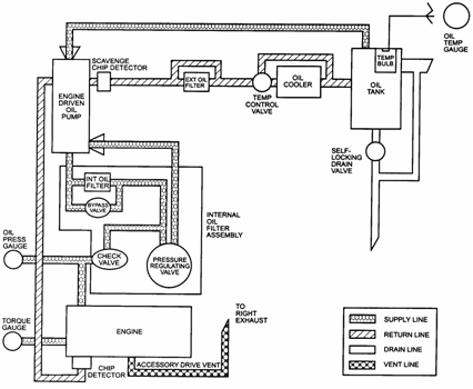 Environmental conditions encountered in TLAs to include: sand, dust, and snow
Landing in any of these conditions will cause problems if you try to hover, so all landings should be quick no hover landings with some forward momentum to keep you out of all the junk your lawnmower blades are kicking up. Equipment malfunction reports
The pilot in command of each aircraft operated in controlled airspace under IFR shall report as soon as practical to ATC any malfunctions of navigation, approach, or communication equipment occurring in flight.
In each report required, the pilot in command shall include:
1. Aircraft ID
2. Equipment affected
3. Degree to which the capability of the pilot to operate under IFR in the ATC system is impaired
4. Nature and extent of assistance desired from ATC Execute missed approach
The controller shall issue instructions to execute a missed approach or to climb and maintain a specific altitude and fly a specified course whenever the completion of a safe approach is questionable because one or more of the following conditions exist:
a. Safe limits are exceeded or radical aircraft deviations are observed.
b. Position or identification of the aircraft is in doubt.
c. Radar contact is lost or a malfunctioning radar is suspected.
d. Field conditions, conflicting traffic, or other unsafe conditions observed from the tower prevent approach completion.
Execution of the missed approach by the pilot is not necessary for conditions a, b, or c above if the pilot has the runway or approach/runway lights in sight.
Execution of the missed approach is mandatory for condition d above. Expected further clearance
The time a pilot can expect to receive clearance beyond a clearance limit. External load ops
Detachable external cargo hook located at the C.G. capable of 1500lbs
Has electrical release, mechanical lease, and another manual on the hook itself.
Clearance not given until cleared by hookup man.
PROCEDURE:
Pattern of 300 and 70kts, execute a normal approach to arrive 10ft AGL into the wind line over the point.
With approximately 100 of straightaway remaining on final, aircrew will begin giving verbal directions to arrive in a hover over load.
Aircrew will then signal ground to hook up the load. Hover adjustments from CC
After load is hooked up and ground personnel are clear, aircrewman will give an all clear and direct pilot to begin lifting. Must lift vertically over the load until slack is gone. At tension on note RADALT. Pilot must lift vertically clear of ground (tension alt plus five feet).
Transition to forward flight and be smooth. Load clears all obsticales by a safe alt (usually 50 to 100 feet).
Climb slowly to 300 AGL while accelerating to 70kts. Aircrew will advise pilot of load position and status. Jettisoning of load may be necessary if oscillations are endangering the helicopter.
Abeam intended point of landing, 300 and 70kts, begin approach to arrive at 90 with 150 to 200 feet AGL and 60kts. Continue decel and descent to intercept approach final at 125 and 45kts and 400 to 600feet straightaway. With approx 100 on final aircrew will begin verbal directions. Control rate of descent and closure.
Plan on terminating approach in a hover ten feet above tension on alt. Aircrew will advise pilot verbally concerning minor hover corrections. Once in hover at crewmans command, begin vertical descent slowly until load is on the ground. Once load is on the deck, crewman will signal pilot to release the load. Failed directional gyro NDB procedures
1. Initiated by pulling the HSI C/B securing power to the HSI and RMI card.
2. Stabilize A/C in straight and level balanced flight. Execute NATOPS procedures.
a. Shift to standby compass scan
b. If IFR, attempt to reestablish VMC"
c. Troubleshoot C/Bs and turn off LAPDS
3. Troubleshoot. Secure landing light, A/C, Pitot heats, Defog blower, Search light (LAPDS) Report problem and request radar service."
4. Turn DIRECTLY inbound or outbound
5. Level the wings and use the wet compass to determine the bearing on which you are located
6. Utilizing bearing/radial intercepts techniques, select an intercept reading heading, then make a standard rate wet compass turn to that heading."
7. Upon intercepting the bearing, apply tracking procedures."
8. Utilize full panel procedures for other maneuvers.
For intercepting bearings inbound:
Put the head of the needle on the 45 degree benchmark, hold this heading until the head falls the number of degrees below the 45 degree benchmark as is the difference between the bearing you were on, and the bearing you are going to."
I.E.: you are inbound on the 180, and want to go inbound to the 210. Turn left to put the head of the needle on the right benchmark. Hold this heading until the head of the needle has fallen 30 ° (210° - 180°) then turn to put head of needle back on top."
For intercepting bearings outbound:
Put the tail of the needle the same number of degrees below the 45 degree benchmark as is the difference between the bearing you were on, and the bearing you are going to, hold this heading until the tail rises to the 45 degree benchmark."
I.E.: you are outbound on the 180, and want to go outbound on the 210. Turn right to put the tail of the needle 30 ° (210° - 180°) below the 45 degree benchmark. Hold this heading until the tail of the needle rises to the 45 degree benchmark then turn to put tail of needle back on top. Failed directional gyro PAR approach
1. Comply with Emergency Procedures described in the magnetic compass turns.
2. Advise controller and request a no gyro PAR or ASR approach Failed directional gyro TACAN approach
1. Initiated by pulling HSI C/B securing power to HIS and RMI card
2. Stabilize A/C in straight and level balanced flight. Execute NATOPS procedures.
a. Shift to standby compass scan
b. If IFR, attempt to reestablish VMC
c. Troubleshoot C/Bs and turn off LAPDS
3. Troubleshoot. Secure landing light, A/C, Pitot heats, Defog blower, Search light (LAPDS) Report problem and request radar service.
4. Level wings and look at tail of the needle to determine radial located
5. Check wet compass for magnetic heading.
6. Set appropriate course into CDI/HSI
7. Utilizing radial intercept techniques, select an intercept heading then make standard rate wet compass turns to that heading.
8. Upon intercepting the bearing, apply tracking procedures
9. Utilize full panel procedures for other maneuvers. FDLP takeoff/landings
1. PNAC checks gauges & lights then gives Landing Signalman Enlisted thumbs up.
2. When cleared, lift to stable 5 hover, PNAC checks gauges & lights and reports Gauges green, no caution lights, clear to slide left.
3. Upon LSE signal, commence level slide perpendicular to the line-up line, maintaining heading until clear of the spot by one rotor diameter.
4. When clear and without stopping in a hover, transition to forward flight. Maintain takeoff power until three indications of a climb (IVSI, RADALD, BARALT) and positive indication of A/S is reported by PNAC.
5. Climb on line-up heading to 200 AGL at 70 KIAS and turn, with proper interval, to arrive on downwind at 300 AGL and 70 KIAS.
6. Just prior to abeam, SNA will make simulated radio call on ICS to the instructor stating aircraft side number, abeam, seat of pilot at controls, and type of approach. Factoryhand 123, abeam, right seat, starboard-to-port. The IP will respond as the shipboard Helicopter Control Officer with deck status, winds, and pitch and roll info.
7. At the 180 ° position, begin a descending, decelerating turn towards the lineup line.
8. Arrive at the 90 ° position with 200 AGL and 60 KIAS.
9. Intercept the line-up line with 800 to 1000 feet of straight-away, 125 to 150 feet AGL, 45 to 55 KTS.
10. Set the appropriate decel attitude and adjust collective to maintain a constant glide slope to arrive over the spot in a 5 foot hover crossing the deck edge at 8 to 10 Field deck landing practice (FDLP) pattern and airspeeds
The field deck landing pattern enables the pilot to practice shipboard landings at an outlying field, (NO FREAKIN WAY!!! REALLY!?!?!?!?)
Pattern altitude is 300 AGL
Pattern airspeed is 70kts.
NAV Lights on Steady Bright means student at the controls.
NAV Lights on Flashing Bright means instructor at the controls. Fire during IMC flight (Engine, electrical, fuselage)
Engine
INDICATIONS:
FIRE light
Smoke
Flames.
PROCEDURES:
WARNING: Be prepared for complete power loss.
*1. Confirm existence of fire.
If fire exists:
*2. Land immediately.
*3. Emergency shutdown - Complete After Landing.
Electrical
INDICATIONS:
Loadmeter shows excessive load
DC voltmeter shows excessive load
Smoke, Fumes, Sparks"
PROCEDURES:
Prior to shutting off all electrical power, the pilot must consider the equipment that is essential to the particular flight environment that will be encountered (e.g., flight instruments and fuel boost pumps)."
Unknown
*1. BAT switch -OFF.
*2. (C) STANDBY GEN switch -OFF.
*3. (C) STBY ATT IND switch - OFF if in VFR Conditions.
*4. MAIN GEN switch -OFF.
If fire persists:
*5. Land immediately.
If fire extinguishes:
*6. Land as soon as possible.
If electrical power is required to restore minimum equipment for continued flight, proceed as follows:
7. All circuit breakers ---Out.
8. (C) Check BAT RELAY circuit breaker - In.
9. BAT switch -ON.
10. MAIN GEN FIELD and MAIN GEN circuit breakers - In.
11. MAIN GEN switch - Reset, then ON.
12. (C) STBY GEN switch - ON.
13. (C) STBY ATT IND switch - ON.
14. Circuit breakers for essential equipment - In One at a Time in Order of importance.
NOTE: Ensure corresponding bus C/Bs are in to provide power to desired equip.
Voltmeter wont ind. bat voltage until bat. bus supply and voltmeter C/Bs
Flight ops can be maintained without bat and gen. 28Vdc inst. inop.
Known
*1. Affected Equipment - Secure.
*2. Affected C/Bs -Pull.
If fire persists:
*3. Electrical Fire Unknown Origin Procedure Execute.
If fire extinguishes:
*4. Land as soon as practicable.
Fuselage
* 1. Land immediately.
* 2. Emergency shutdown -Complete.
WARNING: Fire extinguisher fluid vapors are dangerous and their use should be limited to a well-ventilated area. A moving TH-57 with the cabin vents and windows open is considered to be a well-ventilated area.
Note: A sideslip may be desirable to keep the flame from spreading. Flight control system (from gouge.. not Brim certified!!)
The flight control system is a positive mechanical type, actuated by conventional helicopter controls which, when moved, direct the helicopter in various modes of flight. The system includes the cyclic controls, used for fore-and-aft and lateral control; the collective pitch (main rotor) control levers, used for vertical movement; and directional control (rudder) pedals, used for heading control. The control system forces are reduced to near zero by hydraulic servo cylinders which are connected to the control system mechanical linkages. A force trim system connected to the cyclic and tail rotor controls contains electrically operated mechanical units. There is no force trim connected to the TH-57B tail rotor controls.
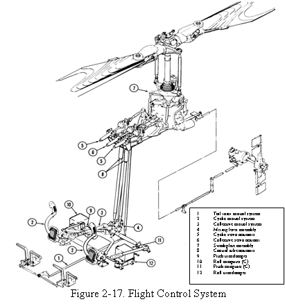
The flight control system consists of push-pull control tubes and bellcranks, actuated by conventional helicopter cyclic, collective, and rudder controls. The controls are routed beneath the pilot seats aft to the center of the helicopter and then up to the cabin roof through the control column, which also serves as a primary cabin structure. Access doors are located on the aft side of the control column, and removable seats are provided for control inspection and maintenance accessibility. Cyclic and collective controls are routed to the main rotor blades through the swashplate. The swashplate and support assembly encircle the mast directly above the transmission. The swashplate is mounted on the universal support (pivot sleeve and uniball), which permits it to be tilted in any direction. Movement of the cyclic control stick results in a corresponding tilt of the swashplate about the uniball, which tilts the rotor tippath plane. Movement of the collective pitch lever actuates the sleeve assembly, which raises or lowers the swashplate and transmits collective pitch changes to the main rotor blades. The cyclic controls are properly coordinated with the collective control by action in the mixing lever at the base of the control column. The directional control (rudder) linkages are routed through the tailboom to the tail rotor. Fixed-length control tubes and a minimum of adjustable tubes simplify rigging. All self-aligning bearings and rod ends are spherical Teflon bearings requiring no lubrication.
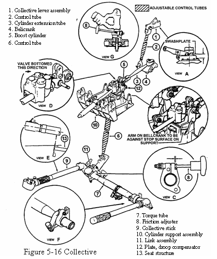
Collective Pitch Control Lever. Acting independently of the cyclic is the collective system (figure 5-16). The collective stick through mechanical linkage transmits pilot inputs to the main rotor blades increasing or decreasing blade pitch angle equally and in the same direction. The collective stick located to the left of the pilot is mounted to a jackshaft. Also located at the jackshaft mounting point is a friction adjuster. The friction adjuster allows the pilot to adjust the amount of force required to move the collective. Control inputs are transmitted through a lever assembly and control tube up through the control column to the hydraulic servo. From the servo, control tubes connect with the collective lever. Moving the collective stick upward will cause the collective lever to be pulled downward. A downward movement of the collective lever will raise the pivot sleeve and uniball assembly and thus raise the swashplate assembly as shown in figure 5-17.
As the swashplate rises, the pitch angle of both rotor blades is increased equally.
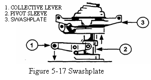
Raising the collective will increase the torque effect and the TH-57, like all helicopters, must have a system to counter torque.
Directional Control Pedals
The TH-57 uses a two-bladed semirigid flapping type tail rotor as an anti-torque device. As shown in figure 5-18, control of the tail rotor is accomplished by control pedals, push-pull tubes, bellcranks, and a pitch change mechanism.
The control pedals, located on the cockpit deck, transmit control inputs by push-pull tubes to the tail rotor. Located with the control pedals is a starwheel adjuster. Rotation of the starwheel adjuster will move the pedals equally closer or farther from the pilot's station. The control linkage, consisting of pushpull tubes, runs from the control pedals rearward up the control column through the tail boom to the pitch change mechanism. The pitch change mechanism mounted to the tail rotor gearbox consists of a lever, control tube, crosshead and pitch change links. The lever extends and retracts the control tube that runs through the tail rotor gearbox and drive shaft.
As the crosshead is attached to the control tube, the crosshead moves in and out. As shown in figure 5-18, the crosshead moving in and out will change the pitch angle of the tail rotor blades via the pitch change link and pitch horns. When left pedal is applied, control tubes are moved and the lever assembly retracts the control tube. As the control tube retracts, the crosshead moves closer to the yoke assembly; tail rotor blade pitch is increased.
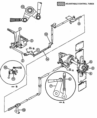 Flight in restricted visibility over water
Might actually be better than restricted visibility over land because when you are over the water, you know that you wont run into towers, buildings, etc. You have all around you to maneuver, including up and down, to find VMC. Flight Information Handbook
The Flight Information Handbook is a DoD Flight Information Publication (FLIP) issued every thirty-two weeks by the National Imagery and Mapping Agency (NIMA) . The Flight Information Handbook contains aeronautical information which is required by DoD aircrews in flight, but which is not subject to frequent change. This publication is intended for U.S. Military use, and procedures herein may not be applicable to other users.
A) Emergency procedures
B) National and International Flight Data Procedures
C) Meteorological information
D) Conversion Tables
E) Standard Time Signals
F) FLIP and NOTAM abbreviations/Codes FLIGHT LINE OPERATIONS (TAXI SIGNALS)
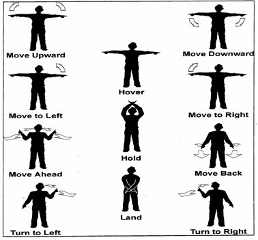 Flight maneuvers in the TH-57C
The TH-57C is IFR certified and its primary purpose is training in both basic and advanced instrument (simulated or actual) conditions as well as introducing basic VFR tactical maneuvering (to include ship board operations).
Certain emergency procedures have additional steps pertaining particularly to the C model. These steps must performed or stated during simulated emergencies. Practice Full autorotations shall not be performed in the TH-57C unless it is an actual power-loss emergency.
With the addition of the MINISTAAB Flight Control System the TH-57C has additional cyclic stability, pitch and roll stability, and altitude hold capabilities. In conjunction with the Force Trim system, the STAB system allows the TH-57C to be a much more stable platform compared to the Bravo model.
Since the TH-57C has more COMM/NAV equipment, AFCS, and other additional equipment compared to the B model, it is considerably more heavy. Special attention should be given to weight limitations, torque limits, and altitude/airspeed restrictions while flight maneuvers are being performed. Fly-by vs. Fly-over waypoints
Fly-by waypoints are used when the aircraft should begin a turn to the next course prior to reaching the waypoint separating the two route segments. Turn anticipation. Approach waypoints except for the MAWP and the missed approach holding waypoint (MAHWP) are usually fly-by waypoints.
Fly-over waypoints are used when the aircraft must fly over the point prior to starting a turn. These are circled waypoints on the approach plates. Fuel system
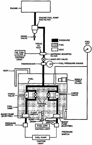 FUEL SYSTEM MALFUNCTIONS
Fuel quantity ind: Land as soon as practicable
Fuel boost pump failure: Fuel pump caution light, indicated pressure of zero
PROCEDURE:
*DESCENT INITIATE TO BELOW 6000
*FUEL PRESS AND QUANT. NOTE
WARNING: 20gals should be considered unusable
WARNING: be prepared for complete power loss is both pumps failed
*FUEL BOOST C/B PULL
*LAND AS SOON AS POSSIBLE
if only one has failed
*FAILED BOOST PUMP IDENTIFY
if unable to identify or fuel low caution
*LAND AS SOON AS POSSIBLE
if able to identify
FAILED BOOST PUMP C/B PULL
LAND AS SOON AS PRACTICABLE
WARNING: if air lead exists in fuel lines total loss of boost could > flameout
Fuel control failure
Erratic Nf, Fluctuating Ng and/or TOT
COLLECTIVE ADJUST
TWIST GRIP ADJUST
LAND AS SOON AS POSSIBLE
WARNING: Be prepared for complete power loss.
Suspected fuel leakage
*TRANSMIT POSITION AND INTENTIONS
*UNNECESSARY ELEC EQUIP SECURE
*LAND AS SOON AS POSSIBLE
When on deck
Shutdown COMPLETE
Helicopter EXIT GCA lost communications
One minute while being vectored, 15 seconds while on ASR final, 5 seconds while on PAR final.
Attempt contact on secondary freq, previously assigned freq, tower, or guard.
If unable to re-establish comms and unable to maintain VMC, proceed with a published approach procedure or previously coordinated instructions. Squawk 7600.
Maintain last assigned or MSA until established on segment of published approach. GCA procedures
1. WAR
2. Navaids
3. Timing
4. Brief Approach
5. Obtain clearance
6. Maintain 100kts until given the instructions Contact final controller At that time transition to 90kts and complete the landing checklist.
7. When directed to turn or descend by the controller, execute as soon as the instructions are received.
a. PAR: starts when the final controller informs the pilot he is on final. When the controller advises the a/c is on glideslope adjust power to establish the predetermined approximate rate of descent while maintaining both airspeed and assigned heading.
b. ASR: when cleared to descend to the MDA, adjust the rate of descent to ensure reaching the MDA before reaching the missed approach point, which is usually located one mile from the landing threshold.
8. Expect landing clearance to be relayed through GCA controller at 3 NM. Geometric imbalance
Because blades flap, individual blade CG locations move in relation to the center of rotation. If it moves outward, it spins slower, if it moves inward, blade spins faster.
If fully articulated, blade can pivot to spin faster or slower at certain regions.
Not in ours, we have underslinging to make it so when blade flaps, C.G. location for each blade stays same relative distance from center of rotation. Glideslope failure
If a glideslope indicator disappears on the CDI/HSI during the approach, descend no lower than published localizer minima, or if not published, no lower than circling minima for your category aircraft. GPS
System is unaffected by weather
Accuracy of 22 meters horizontally and 27.7 meters vertically.
24 satellites ensure that a minimum of 5 are always observable by a user anywhere on earth. Needs 4 satellites to yield a 3D location, needs 5 satellites (or 4 and a baro altimeter) to detect an integrity anomaly (RAIM)
RAIM messages usually indicate there are not enough satellites available to provide the RAIM and or that it has detected a potential error.
If aircraft is greater than 30NM from airport, CDI scale factor is at default 5NM full-scale deflection.
When within 30NM of the airport and there is an approach loaded into the flight plan the unit will transition to approach arm mode and CDI scale will smoothly change to +_ 1.0NM over the next 30 seconds and external annunciator indicates ARM
When within 2 NM from FAF and approach mode is in arm, the unit will transition to approach ACTIVE mode if RAIM is available and in LEG mode. CDI scale will change smoothly to +- 0.3NM and annunciator will indicate ACTV
Automatic waypoint sequencing stops at the MAP. If missed approach is required, manually sequence unit to the missed approach WPT.
When being radar vectored to final remain in OBS mode.
RAIM (Receiver Autonomous Integrity Monitoring) must be available to commence the approach. A flashing message indicator may be an indication of non-availability.
GPS approach authorization limited to U.S. airspace. Use in other airspace requires approval by the FAA Administrator. GPS missed approach
Automatic waypoint sequencing stops at the MAP. If missed approach is required, manually sequence unit to the missed approach WPT. Ground vortex
Benefits of ground effect can be lost at an altitude of less that ½ rotor diameter and A/S between 5 and 20 knots. As helo moves forward, downwash mixes with increased relative wind to create a rotating vortex which eventually causes an increased downwash. HAA/HAT/HAL
HAA (Height Above Airport)
The height of the minimum descent altitude above the published airport elevation. This is published in conjunction with circling minimums
HAT (Height Above Touchdown)
The height of the Decision Height or Minimum Descent Altitude above the highest runway elevation in the Touchdown Zone (first 3000 feet of the runway). HAT is published on instrument approach charts in conjunction with all straight in minumums.
HAL (Height Above Landing)
The height above a designated helicopter landing area used for helicopter instrument approach procedures. Helicopter Point-In-Space (PinS) Approach
PinS nonprecision approaches are normally developed for heliports that do not meet the design standards for an IFR heliport or the heliport is not located within 2,600 feet of the MAP.
A helicopter PinS approach can be developed from conventional NAVAIDs or GPS.
These procedures involve a visual segment between the MAP and the landing area.
To a location 10500 feet or less from MAP, proceed visually or do missed approach
Visual contact is necessary.
To a location 10500 feet or greater from MAP, proceed VFR or do missed approach
Visual contact is not necessary. Helicopter preparation for night operations
Preflight should be conducted during daylight when possible. If not, a white lens flashlight should be used. Red lens will not detect oil and hydraulic leaks.
In addition to normal preflight, pilot must ensure:
external and internal lighting systems are working
rad. alt
stby bat voltage and right seat att ind.
all windows clean
check NOTAMS for limitations on night ops at field
perform Instrument Checklist while taxiing for takeoff High speed approach
1) MAINTAIN 500 AND ACCELERATE TO 100KTS ON THE DOWNWIND
2) AT 180, BEGIN DESCEDING TURN TOWARDS COURSELINE BALANCED
3) ARRIVE AT 90 AT 300 AND 100 KTS
4) INTERCEPT COURSELINE AT 100KTS AND CONTINUE DESCENT TO 50 WITH CROSSWIND CORRECTION.
5) STABILIZE AT 50 AND 100KTS, COORDINATE DOWN COLLECTIVE AND AFT CYCLIC TO SLOW THE A/C WHILE MAINTAINING HEADING.
6) BEGIN THE DESCENT WHEN A 30 TO 45 DEGREE GLIDESLOPE CAN BE MAINTAINED
7) TERMINATE THE APPROACH IN A HOVER OR NO-HOVER LANDING. High Speed Low Level Autorotation (DEMO ONLY)
1) MAINTAIN 500 AND ACCELERATE TO 100 KTS ON DOWNWIND
2) AT FIELD BOUNDARY, BEGIN A DESCENDING TURN TO ARRIVE ALIGNED ON COURSE WITH LANDING AREA AT 100 AND 100 KTS
3) MAINTAIN COLLECTIVE SETTING, SMOOTHLY ROTATE TWIST GRIP TO FLIGHT IDLE. ADJUST COLLECTIVE TO MAINTAIN Nr LIMITS.
4) SMOOTHLY APPLY AFT CYCLIC, FLARE TO DISSIPATE AIRSPEED AND PREVENT SETTLING.
5) AS A/C REACHES CHECKPOINTS OF NORMAL AUTO, COMPLETE NORMAL AUTO PROCEDURES. HOSTAC
Helicopter operations from ships other than aircraft carriers (USN publication) to include our allies and such. Hot seat/hot refuel checklist and procedures
VHF radio OFF
Navigation Equipment OFF
Transponder OFF
RAD ALT CB Pull
C DME CB Pull
Searchlight/landing light OFF
When in the fuel pits:
Twist grip FLT IDLE
C STAB OFF
Crew/passengers Disembark
Monitor UHF radio and make no transmissions, except in an emergency, while the fuel nozzle is attached to aircraft.
COMM/NAV equipment ON
Transponder STBY
RAD ALT CB In
C DME CB In
*Flight controls Check
*COMM/NAV equipment Tune
*TRQ and TOT CBs Pull and reset. Note any exceedence.
*Flight instruments Check
C Normal/recover switch Check
Takeoff Checklist Perform Hot seat procedures
Relieving crew shall inspect the helicopter as possible under existing conditions.
Crew being relieved shall thoroughly brief oncoming crew on all aspects of helo. Hover
1) USE PEDALS TO MAINTAIN HEADING, COLLECTIVE TO MAINTAIN ALTITUDE (5) AND CYCLIC TO MAINTAIN POSITION.
2) SCAN OUT FOR HEADING AND ATTITUDE, DOWN FOR ALTITUDE AND DRIFT, AND IN FOR Nr AND ENGINE INSTRUMENTS.
3) HOVER ALTITUDE OF FIVE FEET IS FROM SKIDS TO GROUND. Hovertaxi
1) DISPLACE CYCLIC IN DESIRED DIRECTION OF MOVEMENT.
2) PEDALS TO MAINTAIN HEADING, COLLECTIVE TO MAINTAIN ALTITUDE, AND CYCLIC TO MAINTAIN RATE OF MOVEMENT
3) TAXI AT A REASONABLE RATE SUCH THAT SAFE LANDING CAN BE MADE IN THE EVENT OF A LOSS OF POWER. HSI or CDI failure
Flags indicate unreliable signal or not operating.
NAV flag is for signal from NAV 1
HDG flag (HSI only) is for compass part.
Fly the needle. (It is your primary anyway) Hydraulic power cylinder malfunction
IND:
Cyclic/collective control displaces to abnormal position, pilot control is dif or imp
PROCEDURE:
*HYDRAULIC BOOST SWITCH OFF
WARNING: will not secure if HYD BOOST C/B is out
*HELICOPTER
REGAIN CONTROL
ADJUST A/S TO COMFORT
*LAND AS SOON AS POSSIBLE
WARNING: if elect failure occurs, system will reenergize in malfunction mode. HYDRAULIC SYSTEM
Designed to reduce operational loads through cyclic and collective.
Power pack: forward left side of xmission driven by xmssn accessory gearbox. Has reservoir that holds one pint gravity fed to pump which pressurizes up to 600+-50psi. Cooled by finned radiator and engine oil cooler blower air.
Filter: Removes foreign matter and has NO BYPASS system. Has red ind. pops
Press. Switch: "Monitors pressure, lights if falls below 300. off when above 400
Solenoid Valve: Spring loaded to OPEN. Electricity needed to CLOSE
Servo Actu: Converts pilot control movements to blade movements. Uses a pilot valve which is mechanically connected to flight controls to adjust amount of fluid into servo to move the actuators which move blade.
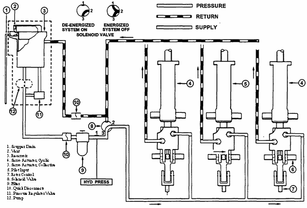 Hydraulic system failure
NOTE: odd or unusual stick forces will be felt in boost off situation. Sliding land is rec.
IND:
Hydraulic pressure light, increased force required, feeback
PROCEDURE:
*AIRSPEED ADJUST TO COMFORTABLE LEVEL
*HYDRAULIC BOOST SWITCH CHECK ON
*HYD BOOST C/B OUT
if system is restored:
LAND AS SOON AS PRACTICABLE
if system is not restored:
HYD BOOST C/B IN
HYDRAULIC BOOST SWITCH OFF
C FORCE TRIM (FT) ON
C AFCS STAB ON
C AFCS ALT OFF
LAND AS SOON AS PRACTICABLE Icing
There are three requirements for the formation of structural icing:
1) outside air temperature below freezing
2) aircraft skin temperature below freezing
3) visible moisture
Clear ice: occurs in cumuliform clouds with appropriate temperatures (0 C to -10 C) where vertical currents can support large drops. Clear ice can form rapidly on aircraft while flying in areas of freezing rain or drizzle.
Rime ice: no as dangerous as clear ice. Rime can be expected in stratiform clouds since vertical currents are not strong enough to support large droplets. Formed through the rapid freezing of small super-cooled water droplets. Most likely to occur at temps between -10 to -20 C.
Frost: a thin layer of crystalline ice that forms on exposed surfaces when the temperature of the exposed surface is below freezing and the dew point is below freezing. Frost forms when both the temperature and dew point are below freezing and they are within about 5 degrees F of each other, the night skies are clear, and the winds are calm.
Icing reporting criteria:
1) TRACE - rate of accumulation is slightly greater than sublimation
2) LIGHT - rate of accumulation may create a problem if flight is prolonged in this environment (over one hour). It does not present a problem if deicing equipment is used.
3) MODERATE - the rate of accumulation is such that even short encounters become potentially hazardous and use of deicing/anti-icing equipment or diversion is necessary.
4) SEVERE - rate of accumulation is such that deicing/anti-icing equipment fails to reduce or control the hazard. Immediate diversion is necessary.
When the Outside Air Temperature (OAT) is below 10 ° C and flight into visible moisture is likely, engine anti-ice and pitot heat shall be on.
Operation of the engine during icing condition could result in ice formations on the compressor front support. If ice were allowed to build up, air flow to the engine would be affected and engine performance decreased. Every effort must be made to remain clear of known icing conditions. The anti-ice system in this helicopter is to be used as a preventative measure only. Once ice has accumulated, the anti-ice system cannot be used as a corrective measure (will not deice). Intentional flight in any known icing condition (<4 ° in visible moisture) is prohibited. For inadvertent flight in icing conditions, proceed as follows:
PROCEDURES:
1. ENG ANTI-ICING -ON.
2. Pitot heat switches -Heat.
3. Alternate static port - As Required.
If unable to remain clear of icing conditions:
4. Land as soon as possible.
WARNING Monitor engine instruments and be prepared for partial or complete power loss. ILS procedures
Same as other approach techniques (WRNTB, 6Ts at IAF and FAF etc)
Intercept final approach course as CDI/HSI begins to center
Intercept glideslope as glideslope indicator begins to center.
During ILS, intercept glideslope by reducing power as GSI begins to center from the top.
No RMI needle (parked at 90/270) so use it for something else
Back up ILS with localizer and timing if need be. Inadvertant IMC at low level
Set the base altitude higher so that you arent doing you turn to 170° still low to the ground. Also be aware that you might not be able to turn 170 ° due to mountains etc. Be aware of your terrain. Inadvertant IMC on night route
Because it is night, this can happen a lot quicker than you think. You might not even know youve gone inadvertent IMC right away. Important thing is to do what you brief in the NATOPS brief. Switch to an instrument scan, try to regain VMC (time for a minute, if not out turn around and time again). Call up approach and get a discreet squawk for an IFR pickup, or squawk 7700, declare emergency, and get vectors home for a PAR / or appropriate location. Inadvertant IMC over water
Might actually be better than restricted visibility over land because when you are over the water, you know that you wont run into towers, buildings, etc. You have all around you to maneuver, including up and down, to find VMC. Initial radio contact with ATC
PTAPTP report if not in radar contact.
Altitude if in radar contact.
CENTER: Call sign and Altitude
APPROACH: Call sign, Altitude, Wx, Request. Inoperative Components or Visual Aids Table
Landing minimums published on instrument approach procedures charts are based upon full operation of all components and visual aids associated with the particular instrument approach being used. Higher mins are required with inoperative components or visual aids as indicated on the charts in the front section of the approach plates. Instrument approach/communications at uncontrolled airports
Most/Some civilians operating at an uncontrolled airport with CTAF arent going to know what the final approach course for the ILS 17 is so tell them something more useful. Bob Sikes traffic, Navy 1E 123 is an orange and white helicopter 5 miles north of the field, inbound at 1700 for a low approach to runway 17, Bob Sikes traffic. Bob Sikes traffic, Navy 1E 123 is an orange and white helicopter executing climbout to the east, Bob Sikes traffic. Instrument autorotation
1. The instructor will initiate the maneuver by rolling the twist grip to flight idle and telling the student he/she has a simulated engine failure.
2. Establish the A/C in a stable auto descent. Adjust nose to 60KIAS and maintain Nr in the green. (94-95% optimum).
3. Turn in the direction of last known wind.
4. Check Ng at flight idle RPM. Report Nr and Ng to your instructor.
5. Ensure harness is locked, simulated mayday report, and simulate transponder set.
6. At 250 above assigned recovery altitude, level wings regardless of into the wind.
7. At 150 above recovery altitude, check collective full down and assume an 8 to 10° nose up attitude. When in the flare, smoothly advance the twist grip to full open and ensure Nr and Nf are married.
8. At 75 above recovery altitude, coordinate up collective and forward cyclic to complete recovery at the recovery altitude with 40KIAS. (R.A. > 1000 MSL)
9. Return to 80KIAS at the recovery altitude. Instrument Takeoff (ITO)
1. With clearance for takeoff and a five-foot hover check completed, the instructor will position the aircraft on the runway aligned with runway heading and transfer the controls.
2. Trim the controls in the neutral position. Smoothly and slowly raise the collective until light on the skids. Adjust the controls to prevent drift. As the aircraft leaves the runway surface, smoothly and slowly lower the nose to no more than 3 ° below the horizon. Simultaneously raise the collective until 5% above hover torque is attained.
3. Maintain takeoff power, confirm you are in a climb, remain wings level, and maintain runway heading with pedals
4. Upon reaching translational lift, smoothly lower the nose to no more than 5 ° below the horizon and recheck torque
5. Maintain runway heading with pedals with wings level until reaching 65 kias
6. Upon reaching 65 kias, center the ball and maintain runway heading with att.
7. Maintain power and attitude until reaching 70 kias. Upon reaching 70 kias maintain 70 kt climb attitude with takeoff power until reaching level off point. The level off point will be computed by subtracting 10% of the climb rate from level off altitude. Instrument takeoff (ITO) checklist
Page 95 of your PCL
1. Set altimeter to current barometric pressure and note altimeter error.
2. After helicopter is lifted into a hover, check turn needles, heading indicators, attitude indicators, and magnetic compasses in a turn to the right and left
3. Check the IVSI for indications of climb and descent.
4. Check airspeed indicators for reading of zero or wind across the deck.
5. Check RADALTs set
6. Check all NAVAIDs, IFF, and radios properly set and tuned
7. Check clock set and running
8. Check engine and transmission instruments normal
9. Check/reset engine rpm at 100 percent
10. Hover check will be performed on the duty runway.
11. IFF to ALT, note time of takeoff, fuel on board at takeoff, and switch to departure control as directed. Jammed flight controls
During ground ops: qualified technicians will inspect immediately (prior to further flight or turnup). No attempt shall be made to free controls. Hold light pressure against jam.
If returned from flight with malfunctions: request immediate flight control inspection. JOG AIR preparation
1:250000 (half the sectional scale)
Rough details on it, used to take us out to boat/or between chart scales (enroute/terminal)
Helpful stuff on it. They do have one for this area.
They have JOG AIR, JOG LAND, JOG SEA charts. Land as soon as possible
Landing at the first site at which a safe landing can be made.
Begin approach to nearest safe landing site
Recite proper procedural steps for emergency
Remind co-pilot to transmit Pan/Mayday call and complete land checklist Land as soon as practicable
Extended flight not recommended. Landing site & duration of flight at discretion of PIC.
Recite critical steps and ask copilot to break out PCL for backup
Advise co-pilot of appropriate landing site choice Landing criteria for emergencies/definitions
Immediately "Self-explanatory. Landing in trees, water, or otherwise unsafe areas should be considered as a last resort."
Possible Landing at the first site at which a safe landing can be made.
Practicable Extended flight is not recommended. The landing site and duration of flight is at the discretion of the pilot in command. Landing zone lighting
Landing zone lights at Santa Rosa are as follows with "O" being orange (amber) light.
O
O
O O O O O O O O O O O O
O O O O O O O O O O O O
O O O O O O O O O O O O
O
O
You will see one of the above four configurations which will tell you landing direction. Just put the tail over the tail of lights sticking out (well, land in the center of the box but, you know what I mean.) Lead and wing aircraft responsibilities and considerations
Section Leader: responsible for all actions of flight whether in the Lead or Wing postion.
Lead: clear the flight, maintain flight in working area, make external calls, provide stable platform for wing.
Wing: maintain good position (be where you are supposed to be), call for maneuvers using brevity codes. Level speed change (BIs)
1. Trim A/C at 80 KIAS on assigned heading and altitude.
2. Reduce collective and adjust wing attitude and pedals to maintain heading and ball centered. Apply aft cyclic to slow to 70 KIAS and stabilize momentarily.
3. Increase collective and adjust wing attitude and pedals to maintain heading and ball centered. Apply forward cyclic to accel to 100 KIAS and stab momentarily.
4. Reduce collective and adjust wing attitude and pedals to maintain heading and ball centered. Apply aft cyclic to slow the aircraft to 80 KIAS and stabilize. Level speed change (FAMs)
1) ESTABLISH 100kts CRUISE FLIGHT AT A GIVEN ALT AT OR ABOVE 500
2) COORDINATE REDUCTION IN POWERWITH AFT CYCLIC TO SLOW TO 70kts MAINTAINING ALTITUDE, HEADING AND BALANCED FLIGHT
3) STABLIZE AT 70, THEN INCREASE POWER AND FWD CYCLIC TO RETURN TO 100kts, MAINTAINING ALT, HEADING, AND BAL FLIGHT. Level standard rate turns
1. Once assigned heading, compute time to turn at a standard rate of 3° per sec.
2. Smoothly roll into required AOB three seconds prior to the time the turn should commence. Check turn needle with ball centered to confirm rate of turn.
3. Check the progress of the turn at least every 15 seconds. Increase or decrease AOB as required to complete turn on time.
4. Lead rollout sufficiently to finish on assigned heading. Leveloff checklist
Page 96 PCL
1. Check OAT and engage anti-ice and pitot heat as required.
2. Engine rpm and power set for desired airspeed
3. Attitude gyros displaying accurate information when cross-checked with other performance instruments.
4. Heading indicator and magnetic compass checked for continuity.
5. Engine and transmission instruments within limits, caution panel checked.
6. Compare airspeed indicators and barometric altimeters for differences.
7. Write down fuel quantity and time.
8. Activate flight plan if required.
9. Compute ETA at clearance limit based on actual takeoff time. LIMITATIONS
Nf
min=97%
max=100% (based on sliding scale TOT,Nf,duration)
Nr
min=90%
norm=90 to 107%
max=107%
trans=107 to 114% (5s)
accel 50 to 60%
Ng
60% to 105% normal
105% max continuous
106% max transient (15 seconds)
TOT
100 to 738 continuous operation
738 to 810 military power range (5 minute)
810 to 843 power transient (6 seconds)
927 max during start, above 810 for 10 seconds"
Torque
continuous=0-85%
military power range=85 to 100%
max=100% (5 minutes)
transient=100-110% (5 seconds)
E Oil Temp
continuous=0 to 107C
max=107C
E Oil Press
min=50psi
max=130psi
50psi below Ng 79%
90psi 79-94% Ng
115psi above 94% Ng
T Oil Temp
continuous=15 to 110C
T Oil Press
min=30psi
max=70psi
continuous=30 to 50psi
Loadmeter
max=70%
Fuel Press
min=4.0psi
continuous=4.0 to 30.0psi
Airspeed
continuous=0 to 130kts
max=130kts
maxauto=100kts
Sideward/Rearward
25/15 when 0-1000DA
20/15 when 1000-2000DA
15/15 when 2000-4000DA
10/10 when 4000-6000DA
5/5 when 6000-10000DA
Maxrateofclimb 50kias
Min IFR speed 65kias
Max speed AFCS OFF:
3000lb and below: 130kias (decr 3.5kias per 1000ft above 3000ft DA)
3001lb and above: 122kias (dec 7.0kias per 1000ft above 3000ft DA)
Max speed AFCS ON or IFR
3000lb and below: 122kias (decr 3.5 per 1000ft above 3000ft DA)
3001lb and avobe: 122kias (decr 7.0 per 1000ft above 3000ft DA)
Max speed doors off: 110kias
Turbulence penetration A/S 80kias
Rotor Engagement Wind Limits: 25 from sides, 40 from front, 17 from back.
Rotor brake 38 to 30% Nr
Altitudes
AFCS OFF below 3000lbs: 20000PA, 18000DA
above 3000lbs: 16000PA, 13000DA
AFCS ON below 3000lbs: 11500PA, 13500DA
above 3000lbs: 8500PA, 11000DA
Climbs/Descents not to exceed 1000ft/min in IMC
Acceleration limits +2.5g and +0.5g at max gross weight
Weight
3,200lbs (3350lbs including external cargo)
CG
106 to 114.2 with AFCS OFF aft limit varies
106.75 to 112.5 with AFCS ON aft limit varies Localizer procedures
Same as other non-precision approach techniques (WRNTB, 6Ts at IAF and FAF etc)
Required altitudes are defined on approach plate as in any other non-precision approach.
Localizer transmitter operates on one of 40 ILS channels between 108.10 to 111.95 MHz.
UHF glideslope trans operates on one of 40 ILS channels between 329.15 to 335.00 MHz
Glidepath projection angle is normally 3 ° above horizontal intersecting MM at about 200 and the OM at about 1400 feet above runway. Normally usable out to 10NM
Localizer provides course guidance throughout the descent path to the runway threshold from a distance of 18 NM from the antenna between an altitude of 1000 feet above the highest terrain along the course line and 4500 feet above the elevation of the antenna site.
When a compass locator is part of the ILS installation, orientation is simply a matter of ADF orientation.
Full scale deflection is 2 ½ ° either side of centerline when outside cone of localizer
In the cone, each dot represents 1 ¼ ° deviation from the localizer course.
Holding: with an ADF for station passage or TACAN type if ILS has DME Lost communications en route
1. During two-way radio communications failure, when confronted with a situation not covered in the regulation, pilots are expected to exercise good judgment in whatever action they elect to take. Should the situation so dictate, they should not be reluctant to use the emergency actions contained in flying regulations.
2. In areas of FAA jurisdiction, should the pilot of an aircraft equipped with a coded radar beacon transponder experience a loss of two-way radio capability, the transponder should be adjusted to reply on Mode 3/A, Code 7600.
3. Pilots can expect ATC to attempt to communicate by transmitting on guard frequencies and available frequencies of navaids.
4. VMC - If able to maintain flight in VMC continue flight under VFR and land as soon as practicable and notify ATC. It is not intended that the requirement to ""land as soon as practicable"" be construed to mean ""as soon as possible"". The pilot retains his prerogative of exercising his best judgment and is not required to land at an unauthorized airport, at an airport unsuitable for the type of aircraft flown, or to land only minutes short of his intended destination. The primary objective of this provision is to preclude extended IFR operations in the air traffic control system in VMC. When operating ""on top"" and unable to descend VMC prior to destination, the procedures contained in paragraph (e) below apply."
5. IMC - If VMC is not encountered, continue the flight according to the following:"
a. ROUTE
i. By the route assigned in the last ATC clearance received
ii. If being radar vectored, by the direct route from the point of radio failure to the fix, route, or airway specified in the vector clearance"
iii. In the absence of an assigned route, by the route that ATC has advised may be expected in a further clearance; or"
iv. In the absence of an assigned route or a route that ATC has advised may be expected in a further clearance, by the route filed in the flight plan."
b. ALTITUDE - At the highest of the following altitudes or flight levels for the route or segment being flown:
i. The altitude or flight level assigned in the last ATC clearance received
ii. The minimum altitude (converted, if appropriate, to minimum flight level) for IFR operations (see Section B, Altimeter Changeover Procedures)"
iii. The altitude or flight level ATC has advised may be expected in a further clearance.
c. LEAVE CLEARANCE LIMIT
i. When the clearance limit is a fix from which an approach begins, commence descent or descent and approach as close as possible to the expect further clearance time if one has been received, or if one has not been received, as close-as possible to the expected time of arrival as calculated from the filed or amended (with ATC) estimated time enroute"
ii. If the clearance limit is not a fix from which an approach begins, leave the clearance limit at the expect further clearance time if one has been received, or if none has been received, upon arrival over the clearance limit, and proceed to a fix from which an approach begins and commence descent or descent and approach as close as possible to the estimated time of arrival as calculated from the filed or amended (with ATC) estimated time enroute"
d. RADAR APPROACHES - initiate lost communications procedures if no transmissions are received for approximately one minute while being vectored to final, 15 seconds while on ASR final approach, or five seconds while on PAR final approach"
i. Attempt contact on a secondary frequency, the previously assigned frequency, the tower frequency, or guard
ii. If unable to re-establish communications and unable to maintain VMC, proceed with a published instrument approach procedure or previously coordinated instructions. Change transponder to appropriate codes
iii. Maintain the last assigned altitude or the minimum safe/sector altitude (emergency safe altitude if more than 25 NM from the facility), whichever is higher, until established on a segment of the published approach Lost communications - NDZ on top
When VMC, maintain VMC and join course rules to either NDZ or NOLF and land.
When IMC, or unable to maintain VMC: (ADEF)
Proceed by the route Assigned in the last ATC clearance received. If being radar vectored, by the Direct route from the point of radio failure to the fix, route, or airway specified in the vector clearance. In the absence of an assigned route, by the route that ATC has advised may be Expected in further clearance, or in the absence of an assigned route or a route expected, by the route Filed on your flight plan.
If being vectored for an approach: Execute that approach.
If being vectored to a South Whiting GCA: Proceed to the IVORY IAF for the ILS RWY 32 approach.
While in the GCA pattern: Attempt radio contact with South Whiting Tower, proceed VFR if able and intercept course rules. If unable, maintain 1700 MSL direct to IVORY for the ILS RWY 32 approach.
While on the South Whiting GCA final: If no transmissions are received by 15 seconds on the ASR or 5 seconds on the PAR RWY 32 final approach, or by 3 DME, attempt radio contact with South Whiting Tower and proceed VFR, if able. If unable, maintain 1700 MSL until the final approach fix (FAF) and proceed with final portion of the NDZ ILS RWY 32.
Radar/Tower shall immediately notify TRACON in the event of lost communications.
Be alert for Tower light gun signals.
NOTE: squawk 7600 and make all calls in the blind. Lost communication procedures at the boat
Attempt to Contact Ship on Secondary Frequency.
Troubleshoot. (obviously not while in the pattern MINIMAL)
Proceed to closest available station.
In the fleet, (for you Navy and Marines at least) you will get the overhead info via message traffic. It will contain the time frame that you are supposed to be on station, what frequencies to use (because all of that is classified and therefore not published) and what theyll expect you to do (which approach youll shoot) if you go lost comms. And they have a light gun to give you those awesome signals. Lost communications procedures on IFR flight plan
Use AVEFAME.
Route: (Assigned, Vectored, Expected, Filed)
Altitude: (Assigned, Min safe, Expected)
If holding, leave at expected further clearance time. (thats why we get one)
If holding and no EFC given, leave when youll get to your IAF as close as you filed for. Lost communication while being radar vectored
If being radar vectored, by the direct route from the point of radio failure to the fix, route, or airway specified in the vector clearance
RADAR APPROACHES - initiate lost communications procedures if no transmissions are received for approximately one minute while being vectored to final, 15 seconds while on ASR final approach, or five seconds while on PAR final approach.
a. Attempt contact on a secondary frequency, the previously assigned frequency, the tower frequency, or guard.
b. If unable to re-establish communications and unable to maintain VMC, proceed with a published instrument approach procedure or previously coordinated instructions. Change transponder to appropriate codes.
c. Maintain the last assigned altitude or the minimum safe/sector altitude (emergency safe altitude if more than 25 NM from the facility), whichever is higher, until established on a segment of the published approach. Lost plane procedures
Do not hesitate to request assistance.
Remain VFR and attempt radio comms on appropriate common, approach, or tower.
Climb for better radio and radar reception.
Last resort, use Guard while squawking 7700.
Dont run out of gas (land with at least 30 min of fuel)
Confess, Climb, Conserve, Communicate, Conform, Consult local area maps, Land Low fuel state during IMC flight
Whenever an aircraft is in a situation where there is not enough fuel for the safe completion of an IFR flight plan it is an URGENT situation. This situation can arise for a number of different reasons: fuel system malfunctions, poor preflight planning, unexpected ATC holding or divert instructions, unforecasted severe weather, or any other unforeseen situation.
According to the Flight Information Handbook, a situation of urgency is defined as a condition concerning safety of an aircraft or other vehicle, or of some person on board or within sight but does not require immediate assistance (e.g. lost, fuel shortage, partial engine failure, etc.)
Transmit an URGENCY CALL or PAN PAN report and use a modified ISPI format. Identification, situation fuel state (fuel remaining in hours and minutes), Position , and intentions. Request assistance or clearance for an approach to a local airport Low level navigation at night
Shall normally take place within local training area.
Contact instructor prior to brief for the route of fight.
Plan heading, time, and distance between each designated checkpoint.
Route shall be flown at 500 to 1000 AGL and between 80 and 100 KIAS.
Terminate route at either Santa Rosa OLF or one of the VFR entry points for NDZ. Low level scan using Radar Altimeter
Set Pilot radalt to ALT 25. Set CoPilot radalt to ALT 50. If it goes off, dont reset horn with the button, fix it!!! Low RPM recovery
Should the terrain preclude landing, execute a lower rotor rpm recovery as follows:
At 15 to 20 feet, crack throttle open slightly
Lower the nose toward the level attitude
Simultaneously increase collective and smoothly rotate twist grip full open
Maintain a 5 foot air taxi
Do not allow Nr to decay below 90 percent
WARNING: tail rotor effectiveness may be lost if Nr is allowed to decay below 80
WARNING: rapid application of twist grip to the full open with Nr below 90 may induce loss of yaw control and tail rotor authority
CAUTION: Exercise extreme caution to avoid exceeding torque limitations. LSE signals
The LSE provides directional and informational signals to the pilot. He is a critical link during shipboard evolutions as he provides clearance and lineup information in situations where the pilot has few visual references or a limited field of view.
Note:
The ultimate responsibility for the safety of the aircraft and crew remains with the pilot in command.
LSE signal to hold or wave off are mandatory. All other signals are advisory. Magnetic compass turns
1. Instructor will initiate maneuver by covering gyro or securing its electrical power.
2. Stabilize A/C straight and level and balanced. Execute NATOPS E.P.
a. Shift to partial panel scan
b. Attempt to regain VMC if IFR
3. Trouble shoot. Secure searchlight, landing light, ecs, defog blower, and pitot heat. Report problem and request radar service.
4. When assigned a heading, determine the shortest direction to turn and proper rollout heading based on magnetic compass latitude error and AOB lead.
5. Roll into a standard rate turn in balanced flight.
6. Scan instruments to ensure proper altitude and airspeed is maintained. Occasionally check magnetic compass for rollout heading.
7. Roll wings level upon reaching rollout heading. Stabilize the A/C straight and level in balanced flight
8. Check magnetic compass for intended heading. Make final corrections utilizing timed half standard rate turns. Maintain assigned heading and balanced flight.
Remember the lead/lag techniques from FTI cat II page 4-15 part C!!! MAIN DRIVE SHAFT FAILURE
Barbell shaped driveshaft with flexible splined couplings at each end (K flex) is installed between free wheeling unit coupling on the engine and the xmission input adapter
Flexible to allow momentary misalignment due to movement of the xmission in flight
Indications:
Nr decreasing, Nf/Ng rpm increasing, left yaw, loud bang/noise
Procedures:
*AUTOROTATE
*TWIST GRIP ADJUST to maintain Nf/Ng in operating range
WARNING: engine must continue to operate to provide tail rotor drive. Nf>80
when on deck:
*EMERGENCY SHUTDOWN COMPLETE Maneuver complete reports
Will be performed at the completion of each maneuver during BI phase.
1. Report maneuver complete
2. Check gauges
3. Scan caution panel lights (including clear chip light)
4. Check the fuel quantity
5. Note the time
Maneuver complete, gauges in the green, no caution lights, fuel 45 gallons, time 1345. Marker beacons
OM = aircraft at appropriate altitude on the localizer course intercepting ILS glidepath. Modulated at 400 Hz and identified with continuous dashes at the rate of two dashes per second and a blue marker beacon light.
MM = aircraft at approximately 3500 feet from landing threshold. Approximately 200 feet above the elevation of the touchdown zone. Modulated at 1300 Hz and identified with alternate dots and dashes keyed at 95 dot/dash combos per minute and an amber marker beacon light.
IM = aircraft at designated DH on the glidepath between IM and landing threshold. Modulated at 3000 Hz and identified with continues dots keyed at six dots per second and a white marker beacon light. MAST BUMPING
Occurs when the rotor exceeds its critical flapping angle and the underside of the rotor hub contacts the rotor mast. If contact is severe enough, mast structural failure can occur. Excessive rotor flapping can also cause rotor blade contact with tail boom or cockpit
Generally occurs at the extremes of the operating envelope.
The most influential causes:
Low G Maneuvers (below 0.5)
Rapid, Large cyclic motion (Especially forward)
Flight near longitudinal/lateral CG limits
High slope landings
Less influential causes:
Max sideward/rearward flight
Sideslip
Blade stall conditions.
WARNING: Should it occur in flight, catastrophic results are highly probably. Since conditions are cumulative, improper correction techniques can aggravate situation.
INDICATIONS:
Sharp, two rev knocking
PROCEDURES:
During Highspeed sideward or rearward flight:
*CYCLIC IMMEDIATELY APPLY SMOOTHLY TOWARD CENTER
*PEDALS IMMEDIATELY APPLY TO ALIGN NOSE
*LAND IMMEDIATELY
During other flight conditions
*CYCLIC IMMEDIATELY APPLY AFT FOR +G, THEN CENTER LAT.
*CONTROLS AS REQUIRED TO REGAIN BALANCED FLIGHT
*LAND IMMEDIATELY
START/SHUTDOWN:
Cyclic: Move to stop bumping
REAR/SIDE FLIGHT
Cyclic: Move slightly toward center
Pedals: Align nose with direction of travel
SLOPE LANDING
Cyclic: Move toward center to stop bumping; reestab hover
ENGINE FAILURE@HIGH FORWARD AIRSPEEDS
Cyclic: Move aft to maintain +G, retain Nr, avoid it in auto
Collective: As required to maintain Nr.
LOW G MANUEVERS (other than nose high)
Cyclic: Aft, then center laterally to regain +G on rotor, maintain Nr
NOSE HIGH, LOW A/S
Collective: Judiciously increase, if possible
Pedal: As required
Cyclic: Neutral Maximum glide auto
1) EXECUTE AN AUTO AT 50 TO 55 KTS. NOTE THE GLIDE DISTANCE
2) ENTER ANOTHER AUTO AT 75 KTS.
3) MAINTAIN ENTRY A/S AND ROTOR RPM AS IN THE 50 TO 55kts AUTO
4) AT 100 SLOWLY RAISE NOSE, TRADE A/S FOR DISTANCE
5) AT 50 TO 55kts AND 75 FLARE AND COMPLETE AUTO. NOTE INCREASE IN GLIDE DISTANCE. Maximum load takeoff
1. HOVER INTO THE COURELINE AT 5, CHECK AND STATE POWER (Ng) REQUIRED TO MAINTAIN A HOVER. THIS IS MAX POWER PERMITTED
2. MAKE A CLEARING TURN AND LAND
3. RAISE COLLECTIVE UNTIL A/C IS JUST CLEAR OF THE GROUND
4. BEGIN SLOW FORWARD MOVEMENT, REMAIN IN GROUND CUSHION
5. DO NOT EXCEED MAX POWER BUT ADD POWER AS NECESSARY TO PREVENT SETTLING. DO NOT RUSH INTO FORWARD FLIGHT. PEDALS
6. WHEN PASSING THRU TRANSLATIONAL LIFT, ADJUST CYCLIC TO PREVENT CLIMB, CONTINUE WITH NORMAL TRANSITION TO FWD FLIGHT.
7. COMPLETE WHEN 40KIAS IS ATTAINED AT NO HIGHER THAN 20 Mechanical versus virtual axis
When tip path plane shifts in response to a control input, virtual axis shifts, while mechanical axis lags behind. As C.G. attempts to align with the virtual axis, the mechanical axis shifts and the aircraft accelerates.
Can cause pilot induced oscillations due to the lag. Minimum safe altitudes/emergency safe altitudes
MSAs are expressed in feet above mean sea level and normally have a 25 NM radius; however, this radius may be expanded to 30 NM if necessary to encompass the airport landing surfaces.
When established, sectors may be no less than 90° in spread. MSAs provide 1,000 feet clearance over all obstructions but do not necessarily assure acceptable navigation signal coverage.
EMERGENCY SAFE ALTITUDES - Altitudes depicted on approach charts which provide at least 1,000 feet of obstacle clearance in non mountainous areas and 2,000 feet of obstacle clearance in designated mountainous areas within a 100 mile radius of the navigational facility upon which the procedure is predicated and normally used only in military procedures. These altitudes are identified on published procedures as ""Emergency Safe Altitudes"". Minimum Vectoring Altitude
Established for use by ATC when they are vectoring you. Provides 1000 feet of clearance in nonmountainous and 2000 feet in mountainous. 300 feet above floor of controlled airspace. Ministab operation
The AFCS system is a basic three axis system (pitch, roll, yaw) with force trim designed to provide attitude retention and to smooth pilot input to the controls (rate dampening). It also provides altitude hold in cruise flight (above 40 KIAS).
There are pitch & roll actuators located at the top of the control tubes which provides input to the hydraulic servo pilot valves. Therefore they have a output force. The pitch & roll computers provide a signal to the actuators which move about a neutral point (0.5 inch total movement NATOPS, 1.0 inch total movement Systems Book) to maintain attitude (ie. Attitude retention).
The Yaw actuator is connected to the tail rotor control tube. Since the tail rotor flight controls do NOT have hydraulic boost, the tail rotor actuator is larger and has a temperature cutoff switch.
The Trim Damper Units (TDUs) provide force trim & smoothes / dampens pilot input. Pitch and Roll FT switch in on the cyclic, Yaw FT is on the anti-torque pedals.
Attitude retention of the AFCS system goes into standby (Integrated Cut Off, ICO) when at least 1 of the following conditions occur:
1. Pilot moves cyclic or pedals (Note: ICO will only occur in the channel pitch roll yaw, affected by the control movement unless you are above 40 knots and then a roll ICO will cause a yow ICO as well. Pitch and Roll Movement is detected by microswitches in the trim damper units and Yaw movement is detected by the microswitches on the pedals themselves.)
2. FT Cyclic button pushed ICOs pitch and roll and if above 40 KIAS, will also ICO the yaw axis as well.
3. FT is turned off
4. Altitude hold engaged will ICO the pitch axis.
Attitude hold (integration) is restored when:
1. Control Inputs stop.
2. FT is on and Cyclic FT button is released.
3. Movement about the axis falls below 1.5o per second.
4. 900 millisecond delay. Missed approach from DH/MDA/circling
DH
A missed approach shall be executed immediately upon reaching the decision height unless the runway environment is in sight and a safe landing can be made. On precision radar approaches, the pilot may expect control instructions until over landing threshold; course and glide path information given after decision height shall be considered advisory in nature.
MDA
A missed approach shall be executed immediately upon reaching the missed approach point if visual reference is not established and/or a landing cannot be accomplished.
Circling
If visual reference is lost while circling to land from a published instrument approach, the missed approach specified for that particular procedure must be followed. To become established on the prescribed missed approach course, the pilot should make an initial climbing turn toward the landing runway and continue the turn until he/she is established on the missed approach course. MOCA/MCA/MRA
MOCA
The lowest published altitude in effect between radio fixes on VOR airways, off-airway routes, or route segments which meets obstacle clearance requirements for the entire route segment and which assures acceptable navigational signal coverage only within 25 statute (22 nautical) miles of a VOR.
MCA
The lowest altitude at certain fixes at which an aircraft must cross when proceeding in the direction of a higher Minimum Enroute Instrument Flight Rules Altitude (MEA).
You must cross the intersection at or above MCA, so determine a point prior to the intersection to begin a standard rate climb (clear it with ATC first) such that you are at or above the MCA before you arrive at the intersection.
MRA
The lowest altitude at which an intersection can be determined. NATOPS CLOSED BOOK EXAM
live by the gouge, die by the gouge
First off, wanna give a shout out to my IFS class leader!! SUP B!!!!!!
Second know the NATOPS (chapter 4 and EPs mostly) but heres some gouge:
TEST A
NATOPS Autorotate procedures
Equipment necessary for IMC
Definition of warning
Definition of shall
Abort start procedures
Minimum IFR speed
In a normal autorotation, Nr and Nf may be matched between ____ and ____%
The engine must continue to operate to provide tail rotor drive effectiveness lost if Nf is allowed to go below ____ percent. (Main Drive Shaft Fail)
Torque limits
Underspeeding procedures
Sprag clutch seizure procedures
Rotor break engagement limits
Hot start procedure
Indications of a fire on shutdown
TEST B
TOT limits
Nr limits
Ng turbine drives what?
Nf turbine drives what?
Tranny oil limits including the note about positive pressure
Definition of caution
Definition of should
Standby Gen limits
Max rate of climbs/decent in IMC
Required equipment for night
Prohibited Maneuvers
Indications of vortex ring state
Trans or T/R chip light means land as soon as ____________
Hot start is probably going to occur if TOT accels past _______ degrees
Hot start procedure
Main drive shaft failure
Tail rotor effectiveness lost if Nf is allowed to go below ___ percent
Sprag clutch slippage procedure
Sustained loadmeter of > _____% could signify an electrical fire.
What three things must you have before leaving flight idle (7-13 top right caution)
During an autorotation Nf/Nr may be matched between ____ and ____ %
Emergency descent procedures
Abort the start if Rotors not turning by ____% Ng or Tranny oil press not rise by _____% Nr
TEST C (never heard anything on test c but Im sure not to dif from A, B)" NDB bearing intercepts (inbound, outbound, wingtip, over the station)
Same as VOR/DME but without CDI NDB orientation
1. Tune and ID the station.
2. Ensure the VOR/ADF needle is in the proper position.
3. Determine the bearing/heading. NDB station passage
When needle swings through the 90/270 position (falls through wingtip) NDZ departure
Departures from NDZ may utilize the Student approach plate departures MONTE-ONE, HUEEY-ONE or BALDI-ONE departures. NDZ on top clearance/ NDZ airwork clearance
1. BI flight may utilize NDZ-on-top, using the Monte 1 for VFR or IFR to the west, HUEEY 1 departure for IFR or VFR to CEW, and BALDY 1 for VFR to the east.
2. All NDZ departures shall utilize the departure route illustrated in the Student Radio Instrument Approach and Departure Plates. After take off, fly RWY HDG until 200'AGL, then the appropriate departure procedures.
3. For VFR on top, all returns are done thru IVORY. Report VFR ON TOP or LEVEL AT 1700. whichever occurs first. Should be cleared to proceed on course, maintain VFR. VFR cloud clearance shall be observed.
4. If not VFR on top by 1700, maintain 1700 and advise departure control of intentions. May request to continue my flight plan, request climb to 5000 or request vectors for an instrument approach to NDZ. If not VFR ON TOP by 5000, request vectors to IVORY for the GCA, ILS or any other approach in use at South Whiting.
5. VFR aircraft may contact Pensacola approach and request the Santa Rosa TACAN 043 approach. NDZ on top weather briefing
If planning an NDZ-on-top flight, a VFR-on-top WX brief must be on board the aircraft and a copy must be left with the ODO before departing.
Valid 2hrs prior to takeoff up to 30 minutes after proposed takeoff time. NDZ stereotype flight plans
100 series are IFR remaining in A-292
200 series are VFR remaining in A-292
300 series are IFR round robin in and out of A-292
400 series are VFR round robin in and out of A-292
500 series are IFR stopover flight plans
600 series are VFR stopover flight plans Night autorotations
Shall only be practiced from the 90 ° or straight in positions.
Searchlight shall be turned on by 200 AGL
Shall only be practiced on a lighted runway with a crash crew on duty.
Shall be power recovery no lower than 10 Night ground procedures
Flash landing light to clear personnel under rotor arc.
Aircraft shall taxi for takeoff from the duty runway and return to line via Spot 1.
Outbound A/C have right of way.
Low work shall be conducted on the South Mat or pads A-E. may enter via 1 or 5 Night hover/hover taxi
Important to keep hover at five feet so AC lights provide illumination.
Shadow size can give good indication of alt.
Tendency is to taxi too fast.
ALL low work shall be conducted with the landing light searchlight on. Night hover scan
Lack of depth perception makes it difficult to maintain altitude and position.
Out portion of scan needs to move closer to the helicopter, where exterior lights have lit up terrain features.
Altitude control is possible by using the shadows produced by the exterior lights. Night visual flight techniques
Visual references are difficult to see at night. The best visual aids for night nav are ground objects that emit illumination (towers with obstacle lights, beacons, etc)
Visual references become worse as altitude increases, or as flight occurs over sparse areas No-hover landing
1. UTILIZE NORMAL OR PRECISION APPROACH PROCEDURES
2. AS THE HELICOPTER APPROACHES GROUND EFFECT USE COLLECTIVE TO CONTINUE THE DESCENT TO A 0 G/S LANDING. No hover takeoff
Enables pilot to safely transition from the ground to forward flight while avoiding dangers of white/brown out conditions cause by loose snow or soil/sand.
1. MAKE A CLEARING TURN IN A NORMAL HOVER THEN LAND
2. TRIM CONTROLS TO NEUTRAL. ESTABLISH HOVER SCAN. SMOOTHLY RAISE COLLECTIVE IN A CONTINUOUS PULL UNTIL REACHING 85% TORQUE 3. AS LEAVE THE GROUND, USE FWD CYCLIC AND MAINTAIN HEADING
4. CONTINUE ACCEL WITH OUTSIDE VISUAL SCAN GAINING A/S TO REACH TRANSLATIONAL LIFT ASAP.
5. AT 40 KIAS, ADJUST POWER, INTERCEPT NORMAL FWD FLIGHT. Normal Approach
1) MAINTAIN 500 AGL AND 70kts ON DOWNWIND
2) AT 180, LOWER COLLECTIVE, BEGIN DESCENDING, DECELERATING TURN TOWARDS COURSELINE MAINTAINING BALANCED FLIGHT
3) ARRIVE AT THE 90 WITH 300 AND 60kts
4) INTERCEPT COURELINE BY 150 WITH 50KTS AND SUFFICIENT STRAIGHTAWAY (600-800) TO INTERCEPT GLIDESLOPE, ESTABLISH CROSSWIND CORRECTION
5) AT 150 SET APPROPRIATE DECEL ATTITUDE AND ADJUST COLLECTIVE TO MAINTAIN 10 TO 20 DEGREE GLIDESLOPE
6) AS HELICOPTER TRANSITIONS TO HOVER, SLIGHT FWD CYCLIC MAY BE NECESSARY TO COUNTER PENDULUM EFFECT.
7) ARRIVE OVER THE SPOT AT HOVER ALTITUDE, POWER AND 0 G/S NOTAMS, Class (I) and (II), D, L, FDC/NOTAM codes
CLASS I: Distribution by means of telecommunications.
CLASS II: Distribution by means other than telecommunications.
D: (distant) information is disseminated for all navigational facilities that are part of the National Airspace System (NAS), all public use airports, seaplane bases, and heliports, listed in the Airport/Facility Directory (A/FD). The complete file of all NOTAM(D) information is maintained in a computer data base at the Weather Message Switching Center (WMSC), located in Atlanta, Georgia. This category of information is distributed automatically via Service A telecommunications system. Air traffic facilities, primarily FSSs, with Service A capability have access to the entire WMSC data base of NOTAMs. These NOTAMs remain available via Service A for the duration of their validity or until published. Once published, the NOTAM data is deleted from the system.
L: (local) information includes such data as taxiway closures, personnel and equipment near or crossing runways, airport rotating beacon outages, and airport lighting aids that do not affect instrument approach criteria, such as VASI.
information is distributed locally only, and is not attached to the hourly weather reports. A separate file of local NOTAMs is maintained at each FSS for facilities in their area only. NOTAM(L) information for other FSS areas must be specifically requested directly from the FSS that has responsibility for the airport concerned.
FDC: (Flight Data Center) On those occasions when it becomes necessary to disseminate information which is regulatory in nature, the National Flight Data Center (NFDC), in Washington, D.C., will issue an FDC NOTAM. FDC NOTAMs contain such things as amendments to published IAPs and other current aeronautical charts. They are also used to advertise temporary flight restrictions caused by such things as natural disasters or large-scale public events, that may generate a congestion of air traffic over a site.
FDC NOTAMs are transmitted via Service A only once, and are kept on file at the FSS until published or cancelled. FSSs are responsible for maintaining a file of current, unpublished FDC NOTAMs concerning conditions within 400 miles of their facilities. FDC information concerning conditions that are more than 400 miles from the FSS, or that is already published, is given to a pilot only on request. NWP 3-04.1
HELICOPTER OPERATING PROCEDURES FOR AIR-CAPABLE SHIPS
Provides a common procedural reference for helicopter operations aboard all US Naval vessels that are air capable. Bridges the gap between the aviation and shipboard sides of the house by giving basic information to the boat guys about your helo. IE, you call up and tell the boat dude that you have a Hydraulic failure. Well, that guy on the boat might not know what the heck that means, so he looks up hydraulic failure and says ah, that means he might have a hard time controlling the A/C. Stuff like that. OPNAVINST 3710.7
Prescribes general flight and operating instructions and procedures applicable to the operation of all naval aircraft and related activities.
Know the OPNAV Option approach
An approach requested and conducted by a pilot which will result in either a touch and go, missed approach, low approach, stop and go or full stop landing. Oscar Pattern
1. Trim the A/C at 80 KIAS on a cardinal heading and assigned altitude.
2. 3s prior, smoothly adjust power to establish standard rate climb or descent. Simultaneously roll the A/C into a standard rate turn to the left or right. Continue for two minutes (1000 of ALT change and 360 ° of turn). Check progress every 15s. Adjust power and AOB as required to complete on time. Maintain A/S.
3. Fifty feet prior to altitude, adjust power, AOB, and att. to level off on params.
4. Trim the A/C at 80 KIAS. Maintain heading and altitude for one minute.
5. 3s prior, smoothly adjust power to establish standard rate descent or climb while simultaneously rolling A/C into standard rate turn (opp other two directions). Continue for two minutes (1000, 360 ° ). Check progress every 15s. Adjust power and AOB as required to complete on time. Maintain A/S.
6. Fifty feet prior to altitude, adjust power, AOB, and att. to level off on params.
7. Trim the A/C at 80 KIAS on new heading and altitude. Overhead time
Time that the ship is expecting you to show up dont be late or theyll leave your butt!
In the fleet, (for you Navy and Marines at least) you will get the overhead info via message traffic. It will contain the time frame that you are supposed to be on station, what frequencies to use (because all of that is classified and therefore not published) and what theyll expect you to do (which approach youll shoot) if you go lost comms. And they have a light gun to give you those awesome signals. Overlay approach
Some published approaches parallel to ground-based NAVAID-based approaches may contain transition points that do not have corresponding waypoints in the associated GPS approach. OVERTORQUE/OVERTEMP/OVERSPEED
If any of the above are observed
Land as soon as possible PAN/MAYDAY REPORTS
PanPan: uncertainty or alert, followed by nature of the urgency
Mayday: indicates imminent and grave danger and that assistance is required
ISPI FORMAT Parade break at homefield
About:
Enables formation flight to separate and gain interval for approach and landing
Description:
Section will be in parade formation at the pre-briefed A/S.
Lead will check Wing in correct position prior to executing break.
Lead will break away from Wing. Wing will break when Lead reaches 45 ° relative bearing line.
Responsibilities:
This is an instructor introduced item ONLY! Partial panel ASR approach
1. Controller will be providing turns to the appropriate directions (turn left)
2. He/She will be advised to make standard rate turns in the pattern and one half standard rate turns on final.
3. Start and stop all turns immediately upon receipt of instructions from the controller. Partial panel straight and level
1. Stabilize the A/C straight and level in balanced flight. Keep attitude corrections and power changes small. Execute NATOPS emergency procedures.
2. Troubleshoot. Secure LAPDS. Report problem and request radar service. Partial panel turns
1. Stabilize the A/C straight and level in balanced flight. Keep attitude corrections and power changes small. Execute NATOPS emergency procedures.
2. Troubleshoot. Secure LAPDS. Report problem and request radar service.
3. WHEN ASSIGNED A HEADING, DETERMINE NUMBER OF DEGREES OF HEADING CHANGE REQUIRED AND THE-RATE OF TURN (STANDARD OR -HALF STANDARD) TO USE.
4. DETERMINE THE TIME REQUIRED TO COMPLETE THE TURN.
5. ROLL INTO A STANDARD RATE TURN IN BALANCED FLIGHT ON A CARDINAL TIME (NOT WITH A THREE SECOND LEAD).
6. SCAN INSTRUMENTS TO ENSURE PROPER ALTITUDE AND AIRSPEED IS MAINTAINED. OCCASIONALLY CHECK CLOCK FOR ROLLOUT TIME.
7. ROLL WINGS LEVEL UPON REACHING ROLLOUT TIME (NOT WITH A THREE SECOND LEAD). STABILIZE THE AIRCRAFT STRAIGHT AND LEVEL IN BALANCED FLIGHT.
8. CHECK MAGNETIC COMPASS FOR INTENDED HEADING. MAKE FINAL CORRECTIONS UTILIZING TIMED HALF STANDARD RATE TURNS. MAINTAIN ASSIGNED HEADING AND BALANCED FLIGHT. Phase lag
Maximum response occurs 90 degrees ahead of maximum period excitation. Pilotage, Dead Reckoning, and Radio navigation techniques
Pilotage: Using ground references (secondary to what we are doing)
Dead Reckoning: Navigating by A/S and timing. (primary what we are doing)
Radio Nav: Using nav aids. Pinnacle takeoff and landings
Perform a power check
Use pattern alt of 300 to 500 feet and 70kts. Make a reconnaissance of LZ. Look for best approach direction and autorotative distances like in the CALs
When abeam, descend and decel to arrive at 90 at 300 and 60kts.
Precision Approach: Anticipate a level off at 300 and continue to decel to arrive 800 to 1000 at 45kts.
Normal Approach: incercept courseline between 150 and 200feet at 50kts and 600 to 800
As intercept the glideslope, reduce power to begin descent.
Adjust angle of descent so tail rotor will clear obstacles by at least 10 feet.
Anticipate sloping or rough terrain and plan on stabilizing in a hover prior to touchdown
No hover landings can be done after one vertical landing has been accomplished
Select best takeoff route optimizing wind effets and obstruction clearance (10 feet min)
After clearing turn, check gauges and lights, increase power and ascent clear of the obstacles and when able, begin smooth accel and transition to forward flight. Pitot-static instrument failure
If the airspeed, vertical speed, or altimeter fluctuates erratically or gives apparently false indications while power and attitude instruments are normal, proceed as follows:
1. PITOT HEAT switch(s) - On.
Monitor cruise power settings and nose attitudes to maintain altitude and airspeed. If pitot heat does not remedy the situation, accomplish the following:
2. (C) Alternate static source knob - Pull.
3. Land as soon as practicable. Pitot-static instruments, alternate static source
Two electrically heated pitot tubes are mounted on the forward part of the cabin nose on either side of helicopter centerline. The right side pitot tube supplies impact air to the pilot airspeed indicator, while the left side pitot tube supplies impact air to the copilot airspeed indicator. Static air pressure for pilot instrument operation is obtained from two lower static vents. One vent is located on each side of the helicopter aft of the chin bubble. The vents supply static pressure to the encoding altimeter, pilot airspeed indicator, altimeter, and instantaneous vertical speed indicator. The pilot system contains an alternate static vent located beneath the copilot seat. The alternate static vent can be selected by pulling the alternate static source knob located on the lower left of the pilot instrument panel. Static air pressure for the copilot instrument operation is obtained from two upper static vents. One vent is located on each side of the helicopter above the pilot static vent. The vents supply static pressure to the air data computer, copilot airspeed indicator, altimeter, and instantaneous vertical speed indicator. POST SHUTDOWN FIRE/INTERNAL
Internal engine fire that occurs in engine that is stopped or coasting down
TOT rises above 400, Flames or smoke coming from engine.
Procedure:
*STARTER ENGAGE
*FUEL VALVE OFF
*IGNITER C/B PULL
*STARTER SECURE after fire is extinguished. Power checks
Compute HIGE/HOGE prior to flight using NATOPS.
Other variables affecting Pr are Gross weight, DA (PA, Humidity, OAT), and wind.
These can contribute to the dif in computed and actual.
Pa can be considered to be 85% or 100% for five minutes due to torque being limit.
For preflight planning, a 10% safety margin between HOGE power required (computed) and power available (100% Q) should be ensured. A planned burn down of fuel may be necessary to achieve this.
Actual torque required to HOGE shall be no greater than 90% before doing CALs POWER REQUIRED EXCEEDS POWER AVAILABLE
When power required for a maneuver exceeds power available, an uncommanded rate of descent will result. Factors that cause or aggravate this situation are:
High G Loading
High gross weight
High Density altitude
Rapid maneuvering
Spool up time from low to high power settings.
Loss of wind effect
Change in wind direction
Loss of ground effect
This condition will be aggravated by rotor droop and loss of tail rotor effectiveness.
Pilot can avoid this by:
Preflight planning to calculate expected performance
Avoiding excessive maneuvering.
Avoiding high descent rates at low altitudes.
Avoiding downwind landings and takeoffs
Maintaining awareness of windspeed and directions
Maintaining awareness of the factors that cause this problem.
RECOVER:
Nr MAINTAIN
RPM switch FULL INCREASE
Airspeed 50 KIAS
Angle of bank LEVEL WINGS
Jettison stores AS REQUIRED<
If impact is imminent: LEVEL A/C to conform to terrain and cushion the landing. POWER SOURCE FOR ALL GAUGES
Voltmeter: 28vDC
Clock: Spring
E Oil Press: wet line
Airspeed: Pitot/Static air
E Oil Temp: 28vDC
Ng: Self Gen
T Oil Press: wet line
Nf/Nr: Self Gen
T Oil Temp: 28vDC
Radar Alt: 28vDC
Fuel Quant: 28vDC
Attitude Gyro: 28vDC
Load Meter: 28vDC
HSI/RMI: 28vDC
Fuel Press: 28vDC
Altimeter: Static air
Torque: wet line and 28vDC
VSI: Static air
TOT: 28vDC
Turn needle: 28vDC
Ball: gravity Practice approaches VFR/IFR
VFR
A simulated instrument approach to an airport for which an approved instrument approach exists shall not be commenced until prior approval has been obtained from the appropriate approach control or, in the case of non-approach control locations, the airport traffic control tower. At non-tower airports, the associated flight service station, if applicable, shall be notified of the simulated instrument approach
IFR
Practice approaches may be commenced with below weather mins provided you dont intend to land there, it is not your alternate or destination, and you have the required mins at your destination and your alternate. Precision minima
Absolute minimums for a single-piloted aircraft executing a precision approach are 200-foot ceiling/height above touchdown (HAT) and visibility 1/2-statute-mile / 2,400 feet RVR or published minimums, whichever is higher. Precision navigation using the Global Positioning System
GPS is for the lazy fools!!! Gimmie an ADF and a VOR and Ill navigate the red route with a stopwatch!!
GPS is a great tool for low level nav because it does not require line of site and at low altitudes line of site might not be that good. Preflight and in-flight fuel planning
All aircraft shall carry sufficient usable fuel, considering all meteorological factors
and mission requirements as computed below:
a. If alternate is not required, able to fly from takeoff to destination airfield, plus a reserve of 10 percent of planned fuel requirements.
b. If alternate is required, fuel to fly from takeoff to the approach fix serving destination and thence to an alternate airfield, plus a reserve of 10 percent of planned fuel requirements.
c. In no case shall the planned fuel reserve after final landing at destination or alternate airfield, if one is required, be less than that needed for 20 minutes of flight, computed as follows:
(1) Reciprocating engine-driven aircraft Compute fuel consumption based on maximum endurance operation at normal cruise altitudes.
(2) Turbine-powered fixed-wing/tilt-rotor aircraft Compute fuel consumption based on maximum endurance operation at 10,000 feet.
(3) Turbine-powered helicopters Compute fuel consumption based on operation at planned flight altitude.
d. Minimum fuel reserve requirements for specific model aircraft shall be contained in the appropriate NATOPS manual. PREFLIGHT EXTRAS IN THE TH57-C
Fuselage Front
NONE
Cockpit
Before turning battery on, put Voltmeter select switch to MAIN BAT
Once battery is on, STBY ATT IND switch ON
Before turning battery off:
Put Voltmeter select switch to STBY BATT.
Make sure standby attitude indicator off flag disappears
Check STBY BATT ON caution light is illuminated and STBY BATT VOLTAGE is >20
NOTE: if <20, a/c is down for IMC flight.
STBY ATT IND switch OFF
Forward Fuselage Right side
NONE
Hydraulic Access Door Right side
Rotor brake master cylinder filler cap SECURE
Transmission Access Door Right side
NONE
Engine Compartment Right side
Rotor brake CONDITION AND SECURITY
Aft Fuselage Right side
NONE
Tailboom Right side
NONE
Tail Rotor
NONE
Tailboom Left side
NONE
Aft Fuselage Left side
Standby battery circuit breaker IN (in baggage compartment)
Engine Compartment Left side
Standby generator CONDITION AND SECURITY
Transmission Access Door Left side
NONE
Hydraulic Access Door Right side
NONE
Upper Fuselage Area
GPS antenna CONDITION AND SECURITY
Rotor System
NONE
Forward Fuselage Left Side
NONE Preparing for an instrument approach
Review the approach prior to the flight. Know how you want to set up all three Navaids (NAV 1, NAV2, ADF), how the IAF, FAF, and MAP are identified. Think of multiple methods for identifying these fixes in case of a Navaid failure. Review all altitudes and restrictions and look on the approach for any specific notes. Prohibited Maneuvers
Aerobatics
Banks exceeding 60deg
Protracted ops in the AVOID and CAUTION areas of the v h diagram
Intentional entry into blade stall or power settling
Hovering turns exceeding 45deg per second Prohibited solo maneuvers
Simulated emergencies
Simulated engine failures (cut guns)
Simulated tail rotor malfunctions
Full or 180 degree autorotations
Sliding landings
Boost-off flight
No-hover landings
Max load takeoffs Pubs carried on BI flights
L 17/18
Volume 19 Approach plates
NOLA Sectional (New Orleans VFR Sectional)
Student Approach Plates
PCL (Pocket Check List)
SAR / On Scene Commander Checklist
Pensacola Area Training Chart
Yankee Brief (DD-175-1, weather brief) Quick Stop
1) MAINTAIN 500 AND ACCELERATE TO 100 KTS ON DOWNWIND
2) AT 180, BEGIN DESCEDING TURN TOWARDS COURSELINE BALANCED
3) ARRIVE AT 90 AT 300 AND 100 KTS
4) INTERCEPT COURSELINE AT 100KTS AND CONTINUE DESCENT TO 50 WITH CROSSWIND CORRECTION.
5) STABILIZE AT 50 AND 100KTS, COORDINATE DOWN COLLECTIVE AND AFT CYCLIC TO SLOW THE A/C WHILE MAINTAING HEADING.
6) SLOW TO 45
7) RECOVER BY UP COLLECTIVE AND FORWARD CYCLIC WHILE MAINTAINING CONSTANT HEADING AND ALTITUDE
8) ACCELERATE TO 70 KTS AND RESUME NORMAL CLIMB. Quick stop from a hover
1) BEGIN A TRANSITION TO FORWARD FLIGHT
2) AT 35 50kts, LEVEL OFF TO STABLIZE A/S AND ALT WHILE MAINTAINING HEADING AND GROUND TRACK.
3) COORDINATE DOWN COLLECTIVE WITH AFT CYCLIC TO SLOW HELICOPTER.
4) SLOW TO APPROX 25kts G/S
5) RECOVER BY COORDINATING UP COLLECTIVE AND FORWARD CYCLIC TO ACCEL TO 50kts, RESUME NORMAL CLIMB AFTER 50. Radar Altimeter Failure
Troubleshoot, check circuit breakers, it might be just your gauge or it could be the antennae and therefore both are busted. Relative motion and radius of turn relationship
Formation flying is nothing more than controlling the relative motion between aircraft. To maintain a fixed position, the relative motion must be stopped. Lead is considered fixed, and any movement between aircraft is considered as movement of Wing in relation to Lead.
Radius of turn:
When Wing has a larger AOB than Lead, Wing will gain on lead (ie distance between Lead and Wing decreases)
When Wing has a smaller AOB than Lead, Wing will fall back (ie distance between Lead and Wing increases) Required equipment for IMC
MAGIC BRN CO
Ministab flight control system (pitch and roll)
2 Attitude indicators (one auto powered by approved standby battery source)
2 Generators (Main and Standby)
Instantaneous vertical speed indicator
Cyclic force trim system
Battery protection circuit
Radar altimeter
1 operable Navigation system appropriate to the routes to be flown
1 operable Communication system
Other equipment as required by the operating rules.
TIN CRAMP (OPNAV stuff)
Turn needle/ball
Icing control equipment if in known or forecasted conditions
Navigations lights.
Clock with hour minute second sweep hand or digital display.
RMI (gyrostabilized mag compass)
Altimeter
Mag compass with current calibration card
Pitot heater and all vacuum pressure instruments. Required equipment for night flight
L(IE) CAR
All Instrument and circuit breaker panel Lights
All Exterior Lights
Operable Communication radio
Attitude gyro
Radar altimeter Required voice reports
ML SWEAT (LE)
Missed approach
Loss of VOR, TACAN, ADF or ILS receiver capability or impairment
Safety of flight
Weather encountering (that was forecasted or not forecasted)
Entering or departing holding or point
Altitude (VFR-On-Top change, leaving an altitude, unable to climb descend 500fpm)
TAS varies by 5% or 10 KTS (whichever is greater) from that filed
Extra required when not in radar contact:
Leaving the FAF for a nonprecision approach or the outer marker for precision approach.
ETA error in excess of 3 minutes from that which was filed. Retreating blade stall
Retreating blade has to increase AOA.
No Lift Areas:
Negative Lift: Positive AOA, but not to a degree which produces appreciable lift.
Negative Stall: rotational flow faster than forward speed however blade flapping is not sufficient to produce positive AOA.
Reverse Flow: rotational velocity slower than forward speed
Indications: Vibrations (2per), loss of long. control and severe feedback in cyclic. Nose of helicopter oscillate up and down.
Varies with A/S, Gross weight, Density alt, G loading, Rotor rpm
Pilot should:
Decrease severity of maneuver (reduces G loading)
Decrease collective pitch (reduces AOA)
Reduce airspeed "(reduces power required, pitch, AOA)"
Descend to lower alt (reduces power required)
Increase rotor rpm (increases rotational velocity)
CAUTION: blade stall could result in structural damage to aircraft. Reverse sensing (CDI and HSI)
When executing a back course localizer approach, reverse sensing occurs in the CDI. Therefore you must fly AWAY from the CDI needle deflection.
HSI will NOT reverse sense if front course is twisted in because the HSI has an RMI card that rotates. ROTOR BLADE STALL
Blade stall occurs when the angle of attach of a significant segment of the retreating blade exceeds the stall angle. When this condition occurs, increased blade pitch will not result in increased lift but may result in increased drag and decreased lift. TH-57 has a warning to the pilot of impending blade stall. Pilot will feel marked increase in airframe vibration and control vibrations.
Threshold of the stall varies with:
AIRSPEED, GROSS WEIGHT, DENSITY ALT, G LOADING, RPM
Increasing two per rev vibration, terminating in a loss of longitudinal control and severe feedback in the cyclic control stick. The nose of the helicopter will oscillate up and down violently, independent of cyclic control stick position.
Recovery may be accomplished by one or a combination of the following actions:
Decrease the severity of the maneuver
Decrease collective pitch
Reduce airspeed
Descend to a lower altitude
Increase rotor RPM Rotor droop
Change in Nf and Nr speeds that occurs with a demand for more power with the governor at a constant speed setting.
Transient: momentary change in Nf and Nr speed resulting from an increased power demand and it is compensated for by the Nf governor.
Steady State: decrease in Nf and Nr speed that results from an increased power demand when the engine is already operating at Max Gas producer speed. This condition should be avoided during normal operations. RPM BEEP CONTROL
Nf rpm (power turbine speed) is set by the pilot using GOV RPM inc/dec switch. Switch opeates an electric linear motor making fine adjustments to the governor throttle lever (96-101 +-0.5%). Protected by GOV CONT C/B SAR
Many Pubs!!
National Sar Manual (JCS 3-50)
Navy Sar Manual (NWP 3-50.1)
SAR TACAID (NWP 3-22.5)
Designed so a pilot can start at the front of the manual and work towards the back, finding all the info needed to execute a search.
Written on the premise that it will be used only for a short-notice SAR scenario.
Not as much detail as SAR Manual.
Time is the most critical element in SAR The three major constraints to time are:
Fuel, Hours of daylight, Human bodys ability to absorb conditions of exposure.
Always assume survivors are incapacitate.
Must wisely manage time.
INITIAL POSITION: probable location of the object for which we are searching.
Two main soruces of noise/uncertainty to the Initial Position:
1. Position error: Represents the accuracy of the Initial Position.
2. Movement error: Represents the effects of Drift.
a. Aerospace Drift: Aircraft glide, ballistic trajectory, parachute drift.
The last two can be found in the SAR TACAID
b. Maritime Drift: Leeway, sea current, wind current, tidal current.
Use of datum marker buoy is most accurate way to determine these.
Can ask a ship for there set and drift.
NAVY SAR MANUAL has leeway of various objects.
c. DATUM: Initial position corrected for movement over time.
d. Whether or not you will find object largely dependant on two things.
Choosing an appropriate Coverage Factor
Choosing and precisely flying an appropriate search pattern. SAR Patterns
Definitions:
Sweep Width (W):
Distance at which a target has the same probability of being detected outside of this range as being missed inside the range.
Values provided in the SAR TACAID are derived from experimentation and SAR after action reports.
Must be corrected for weather, fatigue and aircraft speed.
Track Spacing (S)
This is distance between adjacent parallel search tracks.
A/Cs turning radius and nav accuracy are practical limits as to how much this value can be reduced.
Coverage Factor: (C) = W/S
As an example: if you have the time available to use a Track Spacing equal to the Corrected Sweep Width of your search object, the resulting coverage factor will be one. If you do only one search, your probability of detection will be approx 80%
Since time is a critical factor, tradeoff must be made in probability of detection in order to search the entire area at least once.
The following is one method in determining a reasonable Coverage Factor
a) Determine a DATUM and an estimated SEARCH AREA
b) Determine your limiting time factor (on station time, daylight, exposure...)
c) Using the SAR TACAID, find the largest visual SWEEP WIDTH for the search object and correct it for weather and fatigue.
d) Divide the Search Area by the value from step c. and your limiting time factor. This will be your search speed. If this speed exceeds your helicopters capability, multiply the SEARCH AREA by the limiting time factor and divide by your fastest speed to obtain TRACK SPACING. If this speed is less than 50 knots, use a search speed double that determined and plan to search area twice.
e) Multiply step (c) by the SWEEP WIDTH speed correction factor that is closest to the speed determined in step (d) to obtain W
f) Skip this step if using your helicopters fastest speed. Otherwise, multiply the SEARCH AREA by the time factor and divide by the helicopter speed and W to obtain S
g) Divide W by S to obtain C
h) Using SAR TACAID determine the Probability of Detection.
i) If the search conditions change, repeat the process.
Patterns:
Parallel Patterns:
Description:
Used for a large search area where only approx initial position is known and equal probability the target is anywhere in the search area.
Procedures:
Enter four user defined points in the GPS (corners of the search area)
Enter search area abeam one of the waypoints with an offset equal to ½ S
Fly to point abeam furthest adjacent corner waypoint.
Turn to reenter Search Area abeam waypoint and offset 1½ S
Creeping Line Patterns:
Description:
Specialized version of parallel. Used when probable location of the target is thought to be on either side of a line between two points and there is more chance of the target being in one end of the search area than the other.
Procedure:
Use same procedure as parallel search but enter at the waypoint nearest probably location of search object.
After entering, fly abeam nearest adjacent waypoint offset by ½ S
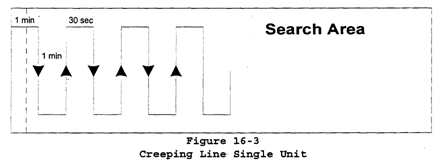
Square Patterns:
Description:
Used to search small area where some doubt exists about the Initial Position.
Provide more uniform coverage than a sector search and may be expanded.
Expanding square search if start from DATUM and go outward.
Procedure:
Enter DATUM into the GPS as user-defined waypoint.
Turn to nearest cardinal radial.
Start clock.
Use TK function to determine crab to track the radial
Track outbound until reaching desired S
Note time, and turn right 90 ° SRT
Start clock.
Upon reaching time for first leg, turn right 90 SRT
Start clock.
Use twice initial timing.
Repeat.
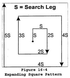
Sector Patterns (V):
Description:
Used when Initial Position is reliable or Search Area is not extensive and a concentrated effort is desired at DATUM because target is hard to detect.
Procedures:
Enter DATUM as user-defined waypoint in GPS.
Turn to nearest cardinal heading.
A 60° search is usually used making nine equal legs.
Upon reaching search radius, turn right and execute a point to point solution to the next inbound radial. Intercept radial and track inbound.
Upon reaching search area radius, turn right and repeat.
To determine distance traveled in a sector search, multiply radius by 9.
To determine total time for a search, divide distance traveled by speed.
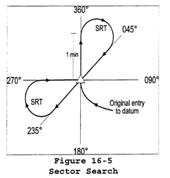 Section high speed approach
Enables the formation flight to execute a high speed approach in formation.
1. 500 AGL and 80 kts with wing in cruise position throughout the maneuver.
2. In the downwind, maintain 500 and accel to 80kts
3. From the abeam position at the downwind field boundary, begin a descending turn to arrive on final with 80kts and level at 50
4. Decelerate to 15 to 20 kts while maintaining 50AGL. Lead intercepts a steep approach glideslope to the intended point of landing and should terminate in a no-hover landing.
5. Announce Harold Crash, Factoryhand 123 and flight, section high-speed approach, right side. Section parade
About:
Employed when there is a requirement for aircraft to fly a fixed bearing off Lead in close proximity and maximum maneuverability is not essential.
Most frequently used during arrival at or departures from ships and airfields, during flight demonstrations and flights using night vision goggles.
Description:
Flown using fixed bearing, lateral distance, and step-up.
45 ° bearing line, 10 feet step-up, one rotor diameter
Far skid toe with near skid aft cross tube, Leads rotor hub below horizon.
Wing shall rotate about Leads axis for turns into Wing.
Wing shall rotate about his own axis in turns from Wing.
Responsibilities:
This is an instructor introduced item ONLY! Section waveoff
About:
Allows either aircraft individually or both aircraft collectively to discontinue an approach and transition to normal climb.
Three conditions:
1. When someone external to the section makes the waveoff call, Lead will make the internal and external calls. Both aircraft will waveoff.
2. Someone internal to the section may call for a section waveoff by calling Mud flight waveoff. Both aircraft will waveoff and Lead will make the external call.
3. If Wing waves off, Wing will make one call using his own side number: Factoryhand 110 waving off, left/right side.
Description:
Ensure twist grip is full open
Increase collective to establish rate of climb. Maintain balanced flight.
If waveoff is called for the section, maintain cruise position relative to lead and execute climb out from field. If waveoff is being executed as a single ship, maintain safe lateral separation from the other aircraft and execute climb out.
Responsibilities:
PAC or PNAC initiates waveoff using appropriate procedures if uncomfortable.
PNAC calls waveoff if glideslope becomes excessive or rate of descent exceeds 800FPM at A/S less than 40kts. Ship NAVAIDS
To enable all weather ops, air-capable ships are normally equipped with TACAN, NDB, and or ASR to facility instrument approved IFR approaches. An air capable ship has a control zone with a radius extending 5nm and 2500MSL.
To ensure smooth transition, some ships are equipped with a Stabilize Glideslope Indicator (SGSI) giving pilot constant glideslope info on final.
1. Pilot shall provide following information.
a. I.D. and type helicopter
b. Position
c. Altitude
d. Fuel state (in time to splash, NATOPS mins
e. Souls on board
2. The controller shall provide
a. Type of approach anticipated (VFR or IFR)
b. Estimated recovery time
c. Altimeter setting, wind, and weather
d. Base recovery course
e. Marshal instructions if required.
f. Steering as required
g. Estimated recovery time. Shipboard approach
1. Lift to stable 5 foot hover, on LSE signal, slide perpendicular to line up line until one rotor diameter from ship. Perform ITO type transition to forward flight.
2. At 200-70kts, turn downwind
3. Establish downwind (300-70kts)
4. Abeam make radio call to instructor (XXX, abeam, right seat, starboard-to-port)
5. Turn to 90 position 200-60kts)
6. Intercept line-up line, 125 to 150 45-55kts.
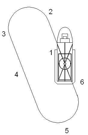 Shipboard Aviation Facilities Resume
This document describes and depicts aircraft landing, VERTREP/hover, and helicopter in-flight refueling (HIFR) facilities aboard air capable and amphibious aviation ships and lighting arrangements aboard aviation ships. The information is intended for use by surface and air type commanders, ships with aircraft capabilities, and aviation groups. Shipboard terminology
ANCHORED- Am orbiting a visible orbit point
ANGELS- Aircraft altitude (in thousands of feet)
ARK- Air droppable life raft
BENT- Equipment indicated is inoperative (temporarily or indefinitely). Canceled by OKAY.
BINGO- Proceed/proceeding to alternate or specified field or carrier. (Not home field or carrier)
BOWWAVE- Weather report giving bases and tops of clouds, wind, visibility, significant weather, sea state
BROWNIE- Photographic devices
BUSTER- Fly at maximum continuous speed (or power)
CANDLE- Night illumination device
CHERUBS- Height of friendly aircraft in hundreds of feet, or fly, or am flying at height indicated in hundreds of feet
COFFEE BREAK- Scheduled communication period
CREW- Any Navy aircraft at scene of action
DATUM- Last known position of a submarine or suspected submarine, after contact has been lost
DAVEY JONES- Survivor in the sea without lifejacket
DAVID- Provide advisory control for search aircraft
DEAF- Any surface ship at scene of action
DUCKBUTT- Aircraft assigned to perform precautionary SAR. Performs secondary role as NAVAID to passing aircraft providing tracking, homing, and steering information, as well as position and weather reports when required
DUFFER- DF-equipped unit
DUMBO- Call sign for amphibious SAR aircraft
ELEVATE- Change altitude to feet
ELLEN- Operate radar continuously
EVERGREEN- Dye marker showing in water
EXCITE- Energize specified equipment
FAMISHED- Have you any instructions or information for me?
FATHER- TACAN
FEAR- Any aircraft or ship at scene of action
FEET DRY- I am, or contact designated is over land
FEET WET- I am, or contact designated is over water
FLOTSAM- Unclassified contact
GADGET- Radar equipment
GOODYEAR- Life raft (followed by number of survivors)
HAWK- Any Air Force aircraft at scene of action I
HIGH DRINK- Helicopter in-flight refueling from a destroyer
HOOKER- Fishing or other small craft
HUGO- Any Army aircraft at scene of action
LIFEGUARD- Submarine or surface ship designated for SAR operations or a submarine or surface ship stationed geographically for precautionary SAR assistance. Also the name of the unit designated to recover a man overboard for vessels conducting alongside operations.
LINK AIRCRAFT- I am calling by flashing light.
LONE RANGER- Dispatch aircraft for independent assignment
MIDDLEMAN- Communication relay that requires receipt and subsequent manual retransmission
MOTHER- Parent ship (usually the parent carrier)
NOCAN- Unable to comply (with instructions)
NOJOY- I have been unsuccessful or I have no information
OKAY- Equipment indicated is operative
ORANGES SOUR- Weather is unsuitable for aircraft mission
ORANGES SWEET- Weather is suitable for aircraft mission
OVERRIDE- Positive control of aircraft is being employed
PARROT- A military IFF transponder
PEDRO- Rescue helicopter
PIGEONS- The magnetic bearing and distance of base for (unit indicated) from you is degrees miles
PLUTO- Call sign for shore-based SAR aircraft
POPEYE- In clouds or area of reduced visibility.
PREVIEW- Advisory control of aircraft is being employed. Aircraft report changes in heading, altitude, and speed.
RESCAP- Rescue Combat Air Patrol; provides protection to rescue vehicles from hostile forces during all phases of SAR
RESCUE- (Location) SAR Coordination Center at (location)
REVERT- Resume search on the previous intercept guard (watch)
RIALTO- Call sign for any or all SAR aircraft
SAR- Search and rescue
SAPPHIRE( )- SAR boat (number)
SCENE COMMANDER- On-scene SAR commander
SICK- Equipment indicated is operating at reduced efficiency
SMOKE- Smoke markers used to mark a position or datum
STRANGER- An unidentified contact not associated with action in progress (bearing, range, and altitude relative to you)
STRANGLE- Switch off equipment indicated
TIFF- (Location) Senior Coordination Center at location
TOOL- Ship that I am calling (Air to Surface)
WELL- Equipment indicated is operating efficiently
X RAY- A ship's ASCAC (call sign)
YELLOW JACKET- Survivor in the sea wearing a lifejacket
ZIP LIP- Hold UHF communication to a minimum Ships communication, NAVAID frequencies and identification
Checking in: When approaching ship, lead aircraft will perform check in.
IX-514, Factoryhand 123, over.
Factoryhand 123, IX-514, go ahead.
IX-514, Factoryhand 123, wingman side number ___, 3 souls each aircraft, 2+00 (time to splash for the the aircraft with the lowest fuel state in the section), with a sweet lock, will report a see you.
Then the flight will make one pass up the starboard side of the ship at altitude (300ft) so the SNA can see the landing environment prior to initial approach and allows the IP to check deck conditions. Lead will then call for the break.
IX-514, Factoryhand 123, abeam for the break.
In the fleet, (for you Navy and Marines at least) you will get the overhead info via message traffic. It will contain the time frame that you are supposed to be on station, what frequencies to use (because all of that is classified and therefore not published) and what theyll expect you to do (which approach youll shoot) if you go lost comms. And they have a light gun to give you those awesome signals. Sidestep maneuver
ATC may authorize a nonprecision approach procedure which serves either one of parallel runways that are separated by 1,200 feet or less followed by a straight-in landing to the adjacent runway.
Cleared ILS runway 7 left approach, side-step to runway 7 right.
Landing mins will be based on nonprecision criteria and therefore higher than precision mins but will normally be lower than published circling mins. Simulated emergencies at altitude (not to include tail rotor malfunctions)
1) INSTRUCTOR WILL INITIATE MANEUVER BY INDUCING OR INFORMING STUDENT OF THE SIMULATED EMERGENCY CONDITION OR SITUATION
2) STUDENT WILL CORRECTLY IDENTIFY EMERGENCY CONDITION OR SITUATION, REPORT DEGREE OF URGENCY IN LANDING A/C, AND BEGIN A PRACTICE APPROACH TO THE NEAREST SAFE LAND SITE
3) STUDENT WILL RECITE CRITICAL PROCEDURAL STEPS TO COMPLY WITH THE EMERGENCY AND ASK INSTRUCTOR TO BREAD OUT PCL
4) STUDENT WILL REMIND COPILOT OF HIS/HER RESPONSIBILTY TO TRANSMIT A SIMULATED PAN/MAYDAY CALL ON ICS AND COMPLETE LANDING CHECKLISTS
5) WHEN AWAY FROM SITE, INITIATE WAVEOFF BY 300 TO BE COMPLETED BY 200 AND NO SLOWER THAN 50KTS
6) AT THE SITE, PRACTICE APPROACHES SHOULD BE TERMINATED IN AN APPROPRIATE LANDING FOR THE EMERGENCY. Simulated engine failure at altitude (at and away from site)
1) INSTRUCTOR WILL INITIATE MANEUVER BY ROTATING TWIST GRIP TO FLT IDLE TO SIMULATE A LOSS OF POWER.
2) LOWER COLLECTIVE TO ENTER AUTO. MAINTAIN BALANCED FLIGHT AND TRANSITION TO APPROPRIATE A/S
3) TURN TOWARD LANDING AREA, AND PLAN FOR IN THE WIND
4) MAINTAIN A/S FROM 50 TO 75 AND Nr FROM 90 TO 107%
5) PAC SHALL DIRECT PNAC TO LOCK, TALK AND SQUAWK
6) AT THE SITE:
a. TERMINATE AS A POWER RECOVERY AUTO UNLESS DIRECTED
b.IF NOT PARALLEL TO COURSELINE BY 150FT, LEVEL WINGS AND CONTINUE AUTO STRAIGHT AHEAD.
7) AWAY FROM SITE: INSTRUCTOR WILL INITATE A WAVEOFF AT OR ABOVE 300 WAVEOFF MUST BE COMPLETED BY 200 AND > 50kts Simulated engine failure hover/hover taxi (cut gun)
1) ESTABLISH INTO THE WIND IN A 5 FOOT HOVER OR TAXI < 5kts
2) HOLD COLLECTIVE PITCH CONSTANT AND MAINTAIN HEADING WITH PEDALS (FREEZE COLLECTIVE, STOP THE YAW)
3) ALLOW A/C TO DSCEND, ELIMATE DRIFT, CUSHION TOUCHDOWN WITH COLLETIVE (ELIMNATE DRIFT AND CUSHION)
4) WHEN ON GROUND, LOWER COLLECTIVE, NEUTRALIZE CONTROLS, WAIT 15 SECS, SMOOTHLY TWIST GRIP FULL OPEN Simulated engine failure on takeoff (DEMO ONLY)
1) START A TRANSITION TO FORWARD FLIGHT AND CLIMB TO AN ALTITUDE AT OR ABOVE 50
2) WHILE MAINTAING THE COLLECTIVE SETTING FOR CLIMB POWER, ROTATE THE TWIST GRIP TO FLIGHT IDLE.
3) COMMENSURATE WITH A/S AND ALT LOWER THE COLLECTIVE AND ADJUST THE NOSE ATT TO CONTROL G/S AND RATE OF DESCENT. MONITOR Nr AND CONTROL WITH THE COLLECTIVE
4) COMPLETE (AS BRIEFED) WITH A POWER RECOVERY OR FULL AUTO Simulated fixed pitch tail rotor at altitude (stuck right and left)
Right:
1) REVIEW NATOPS
2) PATTERN WILL BE FLOWN AT 500. ON DOWNWIND ESTABLISH A/C AT 50KIAS SET POWER TO 30% TORQUE AND CENTER THE BALL TO SIMULATE A STUCK RIGHT PEDAL CONDITION. RESUME NORMAL PATTERN AT 500 AND MINIMUM 60kias.
3) FLY A SHALLOW APPROACH AT 60kias.
4) ON FINAL, WINDS WILL BE CENTERLINE OR LEFT. 50 TO 75 FEET, SET A DECEL. ARRIVE OVER LANDING SURFACE AT 2 TO 3 FEET OR SLIGHTLY ABOVE TRANSLATIONAL LIFT
5) AT 2 TO 3 FEET, ADD COLLECTIVE TO CUSHION LANDING AND LEVEL SKIDS. AS NOSE ROTATES TO THE RIGHT, REDUCE TWIST GRIP TO MAINTAIN ALIGNMENT. RECOVER IN A FIVE FOOT FIVE KTS AIR TAXI OR TO A HARD SURFACE RUNWAY.
Left:
1) REVIEW NATOPS
2) PATTERN WILL BE FLOWN AT 500. ESTABLISH AT 50kias AND 70% TORQUE AND CENTER THE BALL TO SIMULATE A STUCK LEFT PEDAL. RESUME NORMAL PATTERN AT 500 AND MINIMUM 60kias
3) FLY A SHALLOW APPROACH AT 60KIAS
4) ON FINAL, WINDS WILL BE CENTERLINE OR LEFT. MAINTAIN Nr IN THE GREEN AND SIMULTANEOUSLY BEGIN A SLOW DECELERATION IN ORDER TO ARRIVE AT POINT ABOUT 2 FEET ALT AS TRANSLATIONAL LIFT IS LOST. ALIGN HELO WITH LANDING PATH. IF A/C IS NOT ALIGNED AFTER COLLECTIVE APPLICATION, ADJUST TWIST GRIP.
5) ALLOW A/C TO TOUCHDOWN AT NEAR 0 G/S OR RECOVER IN A 5 FOOT 5 KTS HOVER TAXI MAINTAINING ALIGNMENT WITH TWIST GRIP. IF THE A/C HAS AN EXCESSIVE YAW TO THE LEFT AFTER TERMINATING IN A HOVER, EXECUTE STUCK LEFT PEDAL IN HOVER Simulated stuck pedal in a hover (right and left)
Right:
1) REVIEW NATOPS PROCEDURES
2) INITIATE FROM A 5 FOOT HOVER. INSTRUCTOR MAKE A RIGHT PEDAL INPUT TO INITIATE RIGHT ROTATIONS. DETERMINE THE SLOWEST AND FASTEST PORTION OF THE TURN AND KNOW WIND DIRECTION.
3) THE RECOVERY WILL BE INITIATED AS FOLLOWS: AS THE NOSE OF THE A/C PASSES THROUGH THE WINDLINE, REDUCE TWIST GRIP TO SLOW ROTATION.
NOTE: MAY REQUIRE SEVERAL ATTEMPTS
4) ADJUST CYCLIC TO MAINTAIN A LEVEL ATTITUDE AND ELIMINATE DRIFT
5) CUSHION THE LANDING WITH COLLECTIVE.
Left:
1) REVIEW NATOPS PROCEDURES
2) INITIATE FROM A 5 FOOT HOVER. INSTRUCTOR MAKE A LEFT PEDAL INPUT TO INITIATE LEFT ROTATIONS. DETERMINE THE SLOWEST AND FASTEST PORTION OF THE TURN AND KNOW WIND DIRECTIN.
3) RECOVERY WILL BE INITATED AS FOLLOWS: AS NOSE APPROACHES 90 ° PRIOR TO WINDLINE, REDUCE TWIST GRIP AND INCREASE COLLCECTIVE UNTIL ROTATION HAS STOPPED.
NOTE: MAY REQURE SEVERAL ATTEMPTS.
4) COORDINATE COLLECTIVE AND TWIST GRIP TO MAINTAIN HEADING AND ALLOW A/C TO SETTLE. MONITOR Nr AND ELIMINATE DRIFT
5) AFTER TOUCHDOWN, CONTINUE REDUCING TWIST GRIP UNTIL WEIGHT IS GREATER THAN THRUST. Simulated tail rotor failure in a hover (complete loss of tail rotor thrust)
1) DISCUSS NECESSITY FOR SKIDS LEVEL ATTITUDE
2) STABLIZE IN A HOVER HEADING 90 LEFT OF WINDLINE
3) INSTRUCTOR WILL NEUTRALIZE RUDDERS TO COMMENCE RIGHT ROTATION
4) AS A/C COMES INTO WINDLINE, ROTATE TWIST GRIP TO IDLE, HOLD RUDDER AND COLLECTIVE POSITION CONSTANT. ROTATION SHOULD SLOW TO A STOP AFTER TWIST GRIP FLIGHT IDLE. ADDITIONAL STABILTY IS GAINED AS TAILBOOM AND FIN APPROACH WINDLINE AT NINE OCLOCK POSITION
5) CUSHION WITH COLLECTIVE, FOLLOW ROTATION ON THE GROUND WITH RIGHT FORWARD CYCLIC AS NECESSARY. OR HOLD CYCLIC CONSTANT. Sliding Landing
1) UTILIZE NORMAL APPROACH PROCEDURES.
2) INTERCEPT FINAL COURSE LINE, ADJUST NOSE ATT TO DECELERATE BUT MAINTAIN TRANSLATIONAL LIFT (13 to 15kts)
3) AT 5 TO 10 FEET AGL, LEVEL SKIDS TO TOUCH DOWN ABOVE TRANSLATIONAL LIFT WITH 3 TO 15 KTS G/S. PEDALS FOR HEADING
4) SMOOTHLY LOWER COLLECTIVE TO BRING A/C TO GRADUAL STOP. SMOKE AND FUME ELIMINATION
Procedures:
*ECS and DEFOG blower OFF
*VENTS/WINDOWS OPEN
*SLIP or SKID A/C to eliminate
*LAND AS SOON AS POSSIBLE Solo observer responsibilities
Crew should brief prior to seeing ODO
Conduct a crew brief with student pilot
Assist in reviewing the ADB.
If dual solos, sign two acceptance cards, and complete one EFLIR for the combined event
Assist in the preflight inspection.
Challenge student to checklist items and ensure not only responds correctly, but does it."
Ensure doors are secure.
Secure fuel valve incase of a hot start.
Caution student against rapid large flight control movements during flight control checks.
Caution student about exceeding 40% torque
Tune radios
Clear left
Ensure position lights on STEADY BRIGHT
Check caution panel and gauges
Advise student of RPM beep if needed.
Do not allow taxi upwind of starting or shutting down a/c or 50ft from fuel truck
Be alert while taxiing.
Check all overhead circuit breakers in.
Ensure youre A/C clear of all patterns.
Advise if 5 minute torque limits are about to be exceeded.
Keep alert for other A/C
Remind pilot to perform landing checklist
Express concern before it is too late. NEVER COME ON CONTROLS
Report clear below in autos.
Remind student pilot of the solo 90 lane
Power recover TWIST GRIP OPEN
Monitor transmission oil temps. If it reaches 105 during low work, taxi to downwind half and take off.
Pull out checklist during emergencies.
Do not allow twist grip to idle unless both agree.
Hold controls and ensure at flight idle during hot seat
Leave Pace with no less than 20 gals
Dont hesitate to ask for clarification. Solo weather minimums for ANs
1500-3 for both Solo ONAV and AIRNAV
Need this for your departure point, en-route, and destination for AIRNAV
Need this for just departure point and destination for ONAV Sources of weather information
PREFLIGHT:
FSS
Weather Briefers at military bases
Pilot to Metro
Transcribed Weather Brief (TWEB).
INFLIGHT:
FSS (from frequency in shadow boxes on IFR charts)
Enroute flight advisory service (EFAS) on 122.0 Jacksonville Flight Watch, N1E123, Crestview VOR
HIWAS (Hazardous inflight weather service) (H in black circle in navaid boxes)
A continuous broadcast of inflight weather advisories on VOR frequencies including summarized Severe Weather Forecast Alert (AWW), SIGMETs, Convective SIGMETs, Center Weather Advisories (CWA), AIRMETS, and PIREPs.
ASOS (Automated Surface Observation System)
25nm, 10000 feet AGL, VOR freq
SEE FIH
ATIS (Automated Terminal Information System)
Pilot to Metro
update the Flight Weather Briefing Form (DD-1 75-1)
Volmet (voice weather broadcasts)
Meteorological information for aircraft in flight may be obtained through routine and special BHF and HF weather broadcasts
ARTCC (Air Traffic Control Center)
Air Traffic Control Centers have meterologists assigned to them that can provide information to the pilot enroute.
TWEB (T in a black circle in navaid boxes) Generally, the broadcast contains route-oriented data with prepared National Weather Service (NWS) forecasts, inflight advisories, winds aloft, and select current information such as weather reports, NOTAMs, or special notices. At selected locations, telephone access to the TWEB has been provided Special VFR
ATC clearance must be obtained prior to operating within B, C, D, or E when weather is less than required for VFR flight.
Pilot may request and be given clearance to enter, leave, or operate within most D and E surface areas, and some B and C in SVFR, traffic permitting.
MUST REMAIN CLEAR OF CLOUDS.
Visibility requirements (other than helos):
1 SM flight vis in B, C, D, E surface areas."
1 SM ground vis if taking off or landing.
Visibility requirements for helos:
< 1 SM in B, C, D, E surface areas."
Clearance to enter in non tower (E) clearance obtained from nearest tower, FSS, or center
Once out of B, C, D, E surface, ATC does not provide separation.
Prohibited between sunset and sunrise unless pilot is instrument rated and a/c is equipped for IFR flight. Special VFR course rules (at NDZ)
Weather mins are 500-1
In Class C must be at or below 700MSL/500AGL, clear of clouds, south of Langley
Proceed from Point Fish to HWY-90 All other SVFR routing identical to normal
Comms shall include SVFR
No simulated emergencies while in Class C
No SVFR outside local area in Bravo
Searchlight and landing light should be on and position lights steady bright in Class C
SVFR clearance required to reenter Class C SPRAG CLUTCH MALFUNTION
SLIPPAGE: May occur following power off maneuvers when Nr and Nf have been split.
INDICATIONS:
Nf higher than Nr, Low torque, Ng and TOT lower than normal.
PROCEDURES:
*AUTOROTATE
*TWIST GRIP FLIGHT IDLE
if time and altitude permit
*TWIST GRIP SMOOTHLY ROTATE TO FULL OPEN
if Nf/Nr are married:
*COLLECTIVE INCREASE
if sprag clutch continues to slip
*AUTOROTATE
*TWIST GRIP CLOSED
if sprag clutch reengages:
*LAND AS SOON AS POSSIBLE
SEIZUIRE:
INDICATIONS:
Nf/Nr married during shutdown, or above 100% during auto (not 92-96).
PROCEDURE:
*ENSURE TWIST GRIP IS FULL OPEN
*LAND AS SOON AS POSSIBLE
WARNING: if suspected during an auto, waveoff before Nr decays below 85% Square patterns
CONSTANT HEADING
Move laterally in either direction along side of square
Stop at corner, stabilize, move forward on side. Continue all the way around.
PARALLEL
Move forward and place side of square under helo. Turn 90 and begin fwd taxi
Anticipate a hover at the corner, stop, turn 90, stabilize, continue all the way.
When back at starting point, turn 90 inward, and taxi rearward to start point.
PERPENDICULAR
From starting point, begin slow lateral movement in either direction along side
As you reach corner, coordinate cyclic and rudder to turn to a heading perpendicular to next side, do not stop lateral motion.
Continue until reaching starting point. Stab/trim failure at low altitude
Just like if you had this failure at altitude, only problem is now you are lower, and in a flight regime where control is even more important. You are no longer at 1000 feet, you are at 200, so losing 50 feet might be a bigger deal. Stab off approach
1. THE INSTRUCTOR WILL INITIATE THE MANEUVER BY SECURING THE MINISTAB ON DOWNWIND.
2. FLY A NORMAL PATTERN AND TERMINATE THE MANEUVER IN A HOVER FOLLOWED BY A VERTICAL LANDING. Standby battery
22.5 volt, 1.8 ampere hour dry cell battery located in the upper right rear area just aft of baggage compartment near rear bulkhead.
The unit consists of 18 self-contained 1.25-volt nickel-cadmium dry cells and a charging circuit.
EMERGENCY source of power to pilot attitude indicator and its lighting system in the event of a TOTAL electrical failure.
1.5 hours of operation (YEAH RIGHT) when fully charged. Standby generator minimum airspeed
Prolonged operation of the standby generator while it is the primary power supply to the essential No. 1 bus is prohibited at speeds below 65 kts (to obtain proper cooling of standby gen) Standard instrument rating requirements
a. Fifty hours of instrument pilot time under actual or simulated instrument conditions.
b. Successfully complete a NATOPS instrument evaluation in accordance with the NATOPS Instrument Flight Manual.
c. Within the 6 months preceding the date of the instrument evaluation flight obtain:
(1) Six hours as pilot under actual or simulated instrument conditions
(2) Twelve final approaches under actual or simulated instrument conditions, six of which shall be precision approaches and six of which shall be nonprecision.
d. Within the 12 months preceding the date of the instrument evaluation flight:
(1) Twelve hours as pilot under actual or simulated instrument conditions
(2) A total of 18 final approaches under actual or simulated instrument conditions, 12 of which shall be precision and six of which shall be nonprecision.
e. Major flight simulator devices listed by CNO (N889F) may be utilized to meet one-half of the minimum instrument rating requirements.
f. CNATRA is authorized to issue an initial standard instrument pilot rating following successful completion of the naval air training command instrument training syllabus. Standard rate climbs and descents
Same as turns however use 500 ft per minute instead of 3 ° per sec. Standard Terminal Arrival (STAR)
A pre-planned instrument arrival procedure published for pilot use to provide transition from the en route structure to an outer fix or an instrument approach fix/arrival waypoint in the terminal area. STARTER LIMITS
With APU Battery Power
1) 25s ON / 30s Off 40s ON / 60s Off
2) 25s ON / 30s Off 40s ON / 60s Off
3) 25s ON / 30m Off 40s ON / 30m Off
Time is less for APU starts cuz higher amps spool up and heat up starter faster
If light off occurs within first 20s, starter may be operated for 60s with a 60s cooling period. Three such attempts can be made in a 30 minute period, then wait 30 minutes to allow starter to cool. Steep approach
1. MAINTAIN 500, 70 KTS IN THE DOWNWIND
2. SLIGHTLY BEYOND THE 180, LOWER COLLECTIVE AND BEGIN A DESCENDING, DECEL TURN TOWARDS COURSELINE. BALANCED
3. ARRIVE AT 90 AT 300 AND 60
4. STOP DESCENT AND INTERCEPT COURSELINE AT 300 AND 45.
5. INTERCEPT 25 TO 45 DEGREE GLIDE SLOPE, LOWER COLLECTIVE AND START A DESCENT
6. COORDINIATE CYCLIC AND COLLECTIVE TO MAINTAIN GLIDESLOPE
7. TERMINATE IN A HOVER OR NO-HOVER LANDING. Straight and level flight
A flight maneuver where altitude, heading, and airspeed are held constant. Straight-in approach/circle to land
Straight-in approach
An instrument approach wherein final approach is begun without first having executed a procedure turn. Not necessarily completed with a straight in landing or made to straight in landing minimums.
Circle to land
A maneuver initiated by the pilot to align the aircraft with a runway for landing when a straight in landing from an instrument approach is not possible or is not desirable. This maneuver is made only after Air Traffic Control authorization has been obtained and the pilot has established required visual reference to the airport. SUSPECTED FUEL LEAKAGE
Procedures:
*TRANSMIT POSITION AND INTENTIONS
*UNNECESSARY ELEC EQUIP SECURE
*LAND AS SOON AS POSSIBLE
When on deck
Shutdown COMPLETE
Helicopter EXIT TACAN
TACAN is used by the FAA for airways flight and instrument approaches and by the Navy in its tactical control of aircraft.
Provides azimuth and slant range distance (DME)
TACAN station passage is determined when the range indicator stops decreasing (minimum DME)
Must receive DME to receive azimuth in the 57. (can only receive one station at a time)
TACAN procedures
TACAN station passage is determined when the range indicator stops decreasing (minimum DME)
Must receive DME to receive azimuth in the 57
TACAN is susceptible to azimuth errors of 40 ° or multiples thereof (i.e. 80 °, 120 °, etc.). This may be caused by a weak airborne receiver and rectified by merely rechannelizing the unit.
Is about 100 degrees wide for TACAN (40 to 50 degrees for VOR) therefore no TACAN holding at station, but at a point away from station, and use MIN DME for station passage.
Within ½ mile or 3% of distance, whichever is greater out to 199NM
962-1213 UHF, 126X and Y band freq
VOR/DME/TACAN Standard Service Volumes:
T (terminal): From 1000 feet AGL to 12000 AGL out to 25 NM
L (low alt): From 1000 feet AGL to 18000 AGL out to 40 NM
H (high alt): From 1000 feet AGL to 14500 AGL out to 40 NM
From 14500 ft. AGL to 60000 AGL out to 100 NM
From 18000 ft. AGL to 45000 AGL out to 130 NM TACAN approach
1. Before reaching IAF: WRNTB
a. Obtain Weather, Altimeter, and duty runway if atis is not available
b. Request approach
c. Navaids (TINT=Tune, ID, Needles, Twist)
d. Compute Timing as required
e. Brief the approach
2. At the IAF: 6 Ts (Time, Turn, Time, Transition (slow down, come down, landing checks), Twist, Talk)
3. At the FAF: 6 Ts again.
4. If missed approach: PASTTGas
a. Power to 70 KIAS climb/100 KIAS cruise
b. Attitude to 70 KIAS climb/100 KIAS cruise
c. Searchlight off.
d. Turn to comply with missed approach or climbout instructions.
e. Talk. Report missed approach/executing climbout instructions, reason for missed approach, and intentions.
f. Gas. Note fuel quantity. TACAN approaches (LHA/CV)
LHA: Normally equipped with Tacan, NDB, asr/par, and SGSI
Case I: no IMC conditions anticipated on any portion of flight.
Weather mins of 1000 and 3 required.
Report a see you when visual contact is established.
Case II: during daylight when IMC conditions encountered by flights during descent
VMC of at least 500 and 1 exists at ship.
Positive control shall be utilized until the pilot reports see you.
Case III: below case II mins.
Apply to single aircraft only and precision radar shall be used when applicable.
CV: Aircraft Carrier.
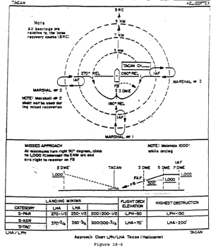 TACAN approaches to air capable ships (DD, AE)
A Primary Marshal approach is a TACAN navigation procedure used to effect a safe letdown to an air capable ship in instrument meteorological conditions (IMC).
Procedures:
1. Hold at primary marshal as directed by radar control.
2. When cleared, pilot shall proceed to IAF using radar vectors, TACAN information, or from holding as depicted
3. The pilot shall report commencing approach and complete landing checklists (6Ts)
4. Proceed to final approach fix and report Landing Checklist complete right/left seat landing
5. PRIFLY shall reply cleared to land and the pilot shall begin a descent to arrive at the missed approach point (MAP) at the minimum descent altitude (MDA)
6. With a SGSI installed, pilot shall report visual acquisition of SGSI to the ship and complete the approach based on SGSI and LSE signals.
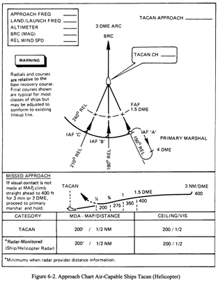 TACAN arcing
1. Proceed to the radial and DME at which the arc begins
2. Turn in the proper direction perpendicular to the present radial.
3. Set the HSI/CDI to the course to be tracked on at the end of the arc.
4. Maintain the desired arc, correcting for wind as necessary until the CDI/HSI begins to center.
5. Turn inbound or outbound on the new radial. TACAN ground speed check
1. Establish heading directly TO or FROM a TACAN station
2. Start the clock and note the DME
3. After 6 minutes note the DME change and multiply by 10. (or 3 and 20, etc) TACAN holding (station and non-station side)
1. TIME (note time on initial arrival over holding fix)
2. TURN (to the appropriate outbound heading)
3. TIME (begin timing when wings level or abeam the fix, whichever occurs last)
4. TRANSITION (slow to 80 KIAS)
5. TWIST (set inbound course in CDI/HSI if TACAN/VOR holding)
6. TALK (make voice report (PTA))
7. After 1 minute or appropriate DME, turn to intercept holding radial/bearing (TAIL-RADIAL-TURN). Track inbound to the fix.
8. Reaching the fix fly the published heading outbound, turn inbound, time if required, intercept radial, note and apply crab correction and track.
9. Reaching the fix, note the time needed to fly inbound, use this info to adjust outbound timing to ensure 1 minute timing inbound. Double the crab correction outbound. Turn inbound and correct subsequent orbits as necessary.
10. Update EFC time at least 5 minutes prior to EFC. TACAN missed approach
Power to 70 KIAS climb/100 KIAS cruise
Attitude to 70 KIAS climb/100 KIAS cruise
Searchlight off.
Turn to comply with missed approach or climbout instructions.
Talk. Report missed approach/executing climbout instructions, reason for missed approach, and intentions.
Gas. Note fuel quantity. TACAN orientation
1. Tune and ID the station.
2. Ensure the VOR/ADF needle is in proper position.
3. Determine the radial/course and DME. TACAN point-to-point navigation
1. Determine whether the present or new fix is farther from the TACAN station
2. Using the directional gyro as a plotting board and its center as the station, place the farther fix on its radial at the edge of the card
3. Determine what fraction the DME of the closer fix is of the farther fix. Place the closer fix on its radial on the directional gyro at a distance from the center of the card equal to that fraction.
4. Connect the two plotted fixes with an imaginary line or a straight edge. Move the line to the center of the directional gyro so that it remains parallel to the original line.
5. Read the no-wind heading where this line crosses the directional gyro.
6. Turn to this heading and apply an estimated wind correction.
7. Repeat the procedure frequently. TACAN radial intercepts
1. Tune and ID the station
2. Determine the bearing/radial you are on
3. Determine the bearing/radial you want to intercept.
4. Measure the angular difference
5. Determine the type of intercept procedure required and turn in shortest direction to commence the intercept.
6. For TACAN/VOR intercepts, set the CDI/HSI to the new course that will be flown after turning to initiate the intercept.
INBOUND
45 degrees or less of bearing/radial change
1. Turn in the shortest direction toward the new bearing/radial to place the head of the needle on the appropriate 45 ° benchmark in the upper half of the RMI. Twist the new course in the CDI/HSI.
2. Note the A/C heading
3. Hold this heading until nearing the new bearing/radial.
4. Turn toward the head of the needle, and apply tracking techniques."
Greater than 45 degrees of bearing/radial change
1. Turn in the shortest direction toward the new bearing/radial to place the head of the needle on the appropriate 90 ° benchmark. Twist the new course in the CDI/HSI
2. Throughout the intercept, either turn as necessary to keep the head of the needle on the wingtip, or approximate the arc by placing the head of the needle 5 ° to 10 ° above the wingtip and maintain heading until it falls 5 ° to 10 ° below the wingtip (ARC)"
3. When nearing the new bearing radial, turn towards the station and apply tracking techniques."
OUTBOUND
45 degrees or less of bearing/radial change
1. Turn in the shortest direction toward the new bearing/radial to place the new bearing/radial under the appropriate 45 degree benchmark in the upper half of the RMI (this puts the tail of the needle in position to rise to the new bearing/radial). Twist the new course in CDI/HSI.
2. Note the aircraft heading. Hold this heading until nearing the desired bearing/radial.
3. Turn back toward the bearing/radial and utilize tracking techniques away from the station.
Greater than 45 degrees but less than 120 degrees of bearing/radial change
1. Turn in the shortest direction toward the new bearing/radial to place the head of the needle on the appropriate 90 ° benchmark. Twist the new course in the CDI/HSI.
2. Throughout the intercept, either turn as necessary to keep the head of the needle on the wingtip, or approximate the arc by placing the head of the needle 5 ° to 10 ° above the wingtip and maintain heading until it falls 5 ° to 10 ° below the wingtip (ARC)
3. When nearing the new bearing/radial, turn away from the station and apply tracking techniques.
Greater than 120 degrees of bearing/radial change
1. Turn directly toward the station and track inbound.
2. After station passage is indicated, turn to parallel the new bearing/radial until the needle stabilizes.
3. Twist new course in CDI/HSI.
4. Using a 15 ° to 30 ° cut, turn to intercept the new bearing/radial and apply tracking techniques. TACAN tracking
1. Turn to the inbound or outbound bearing/radial
2. Apply a wind correction.
3. Correct for drift
4. Establish a track
5. Cross check for drift
6. With TACAN/VOR, set CDI/HSI to tracking course TACH/GEN MALFUNCTIONS
If Nr or Nf indications peg or fluctuate and all other instruments are normal
Land as soon as practicable using other instruments
If Ng falls to zero or fails to rise and fall with power changes:
Monitor other engine instruments.
Avoid high power settings
Land as soon as practicable
Failure of Ng usually accompanied by engine out warning horn and light. Tactical Landing Area (TLA) selection criteria
180°
Abeam at 100AGL and 80KIAS.
Continue level turn and begin to decel to 90 ° position at 100 and 70KIAS
Continue decel to intercept courseline at 100 and 45-65KIAS.
Maintain balanced flight until on courseline
Rate of closure and descent rate are controlled to arrive over point.
90°
Initiate to arrive at 90 at 100 AGL and 70KIAS
Continue decel to intercept courseline at 100 and 45-65KIAS.
Maintain balanced flight until on courseline
Rate of closure and descent rate are controlled to arrive over point. Tail rotor malfunctions and failures
Pilots should guard against grouping all tail rotor malfunctions into one category.
Successful handling involves proper identification of which one, and the steps to correct, plus how the helicopter will react.
There are four basic types of tail rotor malfunctions. Of the basic types, a few generalizations can be made.
1) right rotations: a low powered approach or auto is recommended.
2) Left rotations: a powered approach will usually be possible.
A controllability check at cruise flight should be performed, determining what torque is required for balanced flight.
1) a high torque setting will indicate a stuck left situation
2) a low torque setting will usually indicate a stuck right situation.
FOUR TYPES
1) complete loss of tail rotor thrust:
Causes: Tail rotor driveshaft severed, Loss of tail rotor blades
Reaction: nose will swing to the right in a hover/sideslip in forward flight.
Procedures in a hover:
Twist grip CLOSE
Cyclic ELINATE DRIFT
Collective Increase to cushion landing
Procedures during transition to forward flight:
Twist grip CLOSE
Cyclic ELIMINATE SIDEWARD DRIFT
Collective Increase to cushion landing
Procedures at altitude:
If right rotation is controllable by reducing power to maintain 50 to 70kts:
Set up for auto to a suitable landing area
Autorotate
Twist grip CLOSE
If right rotation is not controllable at 50 to 70 kts:
Autorotate
Twist grip CLOSE
2) fixed pitch right pedal applied:
Causes: pedals locked because of FOD, control linkage failure during right pedal
Reaction: pilot will be unable to control right yaw with pedals. If power is increased, it will aggravate situation.
Procedures in a hover:
If rate of rotation is not excessive and landing surface is smooth:
Collective Decrease to effect a power on landing
If rate of rotation is excessive or landing surface is unsuitable:
Twist grip reduce as nose approaches windline
Cyclic Eliminate drift
Collective increase to cushion landing.
Procedures at altitude:
Maintain A/S and engine RPM to streamline A/C
Plan an approach to a smooth level surface into the wind or slight left crosswind
Establish a shallow approach, maintaining 60kts til final
NOTE: it is not unusual for the nose to be slightly yawed left.
At 50 to 75 feet AGL and when the landing area can be made, start a slow decal to arrive over the intended landing point with min A/S
At approx 2 to 3 feet skid height, increase collective to slow rate of descent and coordinate twist grip to maintain nose alignment
WARNING: a waveoff should be made early.
NOTE: if nose swings right after touchdown, follow turn with cyclic to prevent rolling.
3) fixed pitch left pedal applied:
Causes: Pedals locked because of FOD, linkage failed during left pedal inputs.
Reaction: pilot unable to control left yaw with pedal input. If power is decreased, it will tend to aggravate situation.
Procedures in a hover:
If rate of rotation is not excessive and landing surface is smooth and firm:
Collective Decrease to effect a power on landing.
If rate of rotation is excessive or landing surface is unsuitable for a power on landing:
Twist grip Slowly reduce while increasing collective
Collective Coordinate with twist grip to maintain heading and allow A/C to settle
Procedures at altitude:
Maintain A/S and engine RPM to streamline A/C
Plan an approach to a smooth, level surface into the wind or slight left crosswind"
Establish a normal approach and maintain 60 KIAS during the initial part of approach
On final, maintain engine PRM within limits and begin a slow decel in order to arrive at a point 2 feet above touchdown area"
Apply collective pitch to slow the rate of descent and align helo with landing path. If not aligned, adjust the twist grip to further help. Allow A/C to touch down at near 0 groundspeed maintaining alignment with the twist grip."
NOTE: it is possible for the pilot to slow the A/C to a hover and effect a recovery.
4) Loss of tail rotor effectiveness:
Four characteristics during low speed flight have been identified through flight and wind tunnel tests as contributing factors in unanticipated right yaw. For these to occur, certain wind velocities and azimuths must be present."
1) Weathercock stability (120 to 240)
Winds will attempt to weathervane the nose into the wind.
Comes from the fuselage and vertical fin.
Helo will make an uncommanded turn in either direction unless stopped
It will be accelerated if already yawing when wind enters 120 to 240
Importance of timely corrective action cannot be overstressed.
2) Tail rotor vortex ring state (210 to 330)
Tail rotor puts out bad air to the left of helo
Pilot must make corrective pedal inputs as the changes are recognized
This characteristic presents no significant problem unless not timely corr
3) Main rotor vortex ring state (285 to 315)
Main rotor vortex can be directed into trail rotor changing tail rotor AOA.
Initially its AOA increases during right turn, then decreases."
4) Loss of translational lift (all direction)
Requires increased power demand and therefore increased antitorque.
If it occurs while in a right turn, rate will accelerate as power is incr."
Could result in RPM rotor decay if at max power.
Pilot might not know he has lost translational lift due to watching the yaw.
Pilot might not maintain A/S while making right downwind turn
Pilot must always consider A/C heading, groundtrack, wind dir, G/S"
The A/C can be operated safely in the above relative wind regions if proper attention is given to controlling the A/C.
However, if right yaw is initiated in one of the above regions, the yaw rate may increase unless suitable action is taken."
Procedures:
Pedals
Maintain full left pedal
Collective
Reduce (as altitude permits)
Cyclic
Forward to increase A/S
If spin cannot be stopped:
Autorotative landing EXECUTE. Takeoff/Approach/landing minimums (RWOP/3710.7)
Takeoff
Published mins for the non precision approach to the duty no less than 300-1
Published mins for the precision approach to the duty no less than 200-½
Approach
When reported weather is at or below published landing minimums for the approach to be conducted, an approach shall not be commenced in multi-piloted aircraft unless the aircraft has the capability to proceed to a suitable alternate in the event of a missed approach.
When reported weather is below published landing minimums for the approach to be conducted, an approach shall not be commenced in single-piloted aircraft.
Practice approaches may be commenced with below weather mins provided you dont intend to land there, it is not your alternate or destination, and you have the required mins at your destination and your alternate.
Landing
Minimums for the approach and runway in site and in a position for safe landing. TERF profiles
Nap-Of-the-Earth: Flown as close as vegetation and obstacles permit. Characterized by varying airspeed and altitude as required by terrain, weather, light, and enemy.
Contour: Flown at low altitude conforming to the contour of the earths surface. Characterized by varying airspeed and altitude as vegetation dictates.
Low-level: Flown at a selected altitude at which detection is avoided or minimized. It is preselected and flown at a constant A/S and Alt. Terminal Arrival Area (TAA)
T structure with all waypoints named five character pronounceable.
MAP at the threshold,
FAF 5 NM from the threshold
Intermediate Fix (IF) 5 NM from the FAF.
Two IAF 90 °, 3 to 6 miles from center IF(IAF) (distance based on category a/c)
Holding pattern at the IF(IAF) for course reversal requirements.
Missed approach is ideally aligned with final approach course (direct entry) Terminal procedures
Just like our approach brief enter left downwind, right crosswind, straight in, etc. TORQUE MALFUNCTIONS
If digital torque meter is low or falls to zero with corresponding digital readout than a torque line has possibly ruptured.
Monitor engine instruments
Land as soon as possible
If the indicator falls to zero and the digital readout is blank, loss of electric power
Monitor engine instruments
Check TRQ circuit breaker IN
Land as soon as practicable
Minor torque fluctuations are normal TOT MALFUNCTIONS
If TOT falls to zero or fails to rise and fall with power changes:
Monitor other engine instruments
Avoid high power settings
Land as soon as practicable Transition to forward flight
1) FROM A STABLE HOVER, BEGIN FORWARD MOTION
2) ADD COLLECTIVE TO PREVENT SETTLING, MAINTAIN HEADING
3) CONTINUE TO ACCEL, WING DOWN TOP RUDDER, 20AGL 40kts
4) PASSING 50 AGL 65kts, SET NOSE TO 70kts CLIMB ATTITUDE AND CLIMB AT 500 TO 700 fpm. @ 70kts.
5) 50 PRIOR ADJUST NOSE TO CRUSE ATTITUDE, APPROACH A/S. TRANSMISSION OIL SYSTEM MALFUNCTIONS
On Ground:
If oil pressure is 50 to 70, do not accelerate engine until within limits
If oil pressure is greater than 70, shutdown
Airborne:
If pressure not within normal, or fluctuates: Land as soon as possible
If temperature exceeds red line: Land as soon as possible
If temperature fluctuates or falls to zero: Land as soon as practical Transmission system
Wet sump/pressure lubrication system. Pump driven by accessory drive gear which also drives the hydraulic pump and the Nr tach gen.
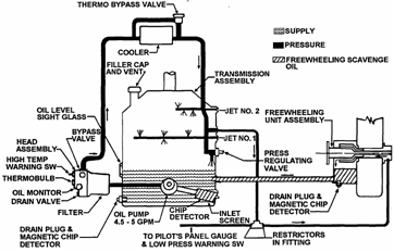 Turbulence penetration
Orographic or mountain turbulence.
Moving air being lifted by natural or manmade obstructions.
Probably severe turbulence several hundred yards downwind of ridge.
Buildings, hangars, and other obstructions can do same.
Can be found near the middle and downwind side of a canyon or gorge.
Approach upwind side parallel to the ridgeline
Avoid downwind side of gorge.
Valleys or Canyons: Increased wind velocities due to venture effect and excessive turbulence near bottom. Turn on the spot/clearing turns
1) FROM A HOVER, BEGIN SLOW TURN BY DISPLACING PEDAL
2) ADJUST CYCLIC TO REMAIN OVER POINT
3) NOSE WILL TUCK AND RATE OF TURN WILL INCREASE AS PASS WINDLINE, USE CYCLIC TO MAINTAIN POSITION AND PEDALS TO CONTROL RATE OF TURN. Turn Pattern
1. Trim aircraft at 80 kias on assigned altitude and cardinal heading.
2. Initiate a turn in either direction utilizing 10 ° AOB for 90 °. After 90 ° of turn, reverse the turn at 10 ° AOB for 90 ° of heading change. Maintain A/S and ALT.
3. Reverse the turn and roll into a 20 ° AOB for 180 °. Reverse turn and come back.
4. Reverse the turn and roll into a 30 ° AOB for 360 °. Reverse turn and come back.
5. Roll wings level on heading altitude and airspeed. Uncommanded right roll during flight below 1 G
IND:
Uncommanded right roll
Reduced cyclic effectiveness
PROCEDURES:
Cyclic: "Immediately Apply AFT to Establish positive G load on rotor, then center."
WARNING: MAST BUMPING
Controls As required to regain balanced flight
Land immediately if mast bumping has occurred. Unusual attitude recoveries (full panel)
1. LEVEL THE WINGS
2. LEVEL THE NOSE
3. CENTER THE BALL
4. SET POWER FOR 80KIAS. STOP ANY CLIMB OR DESCENT, ACHIEVE 80
5. RECHECK WINGS NOSE AND BALL
6. EXECUTE STANDARD RATE CLIMB OR DESCENT TO BASE ALTITUDE
7. EXECUTE LEVEL STANDARD RATE TURN TO BASE HEADING Unusual attitude recoveries (Partial panel)
1. CENTER THE BALL
2. LEVEL THE WINGS AND CHECK THE TURN NEEDLE
3. LEVEL THE NOSE AND CHECK THE IVSI
4. SET POWER FOR 80KIAS, STOP ANY CLIMB/DESCENT, ACHIEVE 80
5. RECHECK BALL, WINGS, NOSE
6. EXECUTE A STANDARD RATE CLIMB/DESCENT TO BASE ALTITUDE
7. EXECUTE LEVEL STANDARD RATE TURN TO BASE HEADING Use of GPS during SAR
GPS is a nice tool for SAR. You can use it to fly a specific track and it will tell you how to stay on that track. It's also nice to fly over a spot and if you want to mark that spot, just hit Save, Enter, Direct, Enter, and now that spot is your "Navaid" Use of lights
Position Lights:
During runup to flight idle: FLASH BRIGHT
Upon reaching flight idle: STEADY BRIGHT
During shutdown from flight idle: FLASH BRIGHT
Cockpit Lights:
During prestart checks: lowest intensity allowing you to read inst.
For non tactical flights above 500 instrument and panel lights may be illum. and then gradually dimmed.
When conducting night flight while referencing instruments:
Lights will be higher intensity until just prior to landing.
Map light may be used to supplement available light in cockpit.
Normally used by nav/copilot to view maps. Check during preflight.
In addition, a flashlight may be used to provide illumination within cockpit.
Anti-collision Lights:
During turnup and shutdown: OFF until crossing hold short line. Back OFF upon clearing duty.
Upon entry into IMC OFF to reduce distraction and disorientation.
Landing Light/Searchlight
Searchlight normally on during all takeoffs and landings during nontactical training
Both may be used when hovering to and from parking spot.
During practice night autos, searchlight is turned on by 200 AGL and left on until termination of maneuver (Caution: unless it reduces vis due to WX)
Searchlight may be used to identify the helicopter position when entering traffic.
Also used to signal the tower controller of a radio failure. USE OF LIMITS
Direct result of the flight test program and experience.
Compliance with the limits will allow pilot to safely perform assigned mission.
If any limits are exceeded, record with a MAF and not fly until inspected. Use of metro, FSS, and flight watch facilities
Pilot-to-Metro Services (PMSV) are available from all Naval Meteorology and Oceanography Command (NAVMETOCCOM) and U. S. Marine Corps (USMC) aviation weather activities. The primary purpose of PMSV is for communicating various types of weather information to pilots. PMSV is also used to update the Flight Weather Briefing Form (DD-1 75-1) and to receive pilot weather reports (PIREPS) of significant or hazardous weather phenomena, which are entered into weather telecommunications networks.
Enroute Flight Advisory Service (EFAS): Call Flight Watch on 122.0 using the name of the of the center controlling your area and closest VOR to you. Jacksonville Flight Watch, Navy 8E123, Crestview VOR Use EFAS to obtain Enroute weather Updates. Use of radar altimeter
KRA-405 receiver/ KNI-416 altimeter indicators/ two KA-54 antennas/ RADALT C/B
Accurate ground info from 2,000 to touchdown. ( -10 feet to 2000 feet )
5 foot increments up to 200 feet
20 foot increments up to 500 feet
100 foot increments up to 2000 feet VASI/PAPI lights
VASI (Visual Approach Slope Indicator):
Visible from 3-5 miles during day, up to 20 miles at night.
Provides safe obstruction clearance within plus or minus 10 ° of extended runway
Most installations consist of 2 bars, near and far, providing 3 degree glide path.
Red over white: on glide path.
PAPI (Precision Approach Path Indicator):
Similar to the VASI but are installed In a single row.
Red lights coming in from the right to tell how high above or how low the approach is Vertical landing
1) SMOOTHLY LOWER COLLECTIVE TO BEGIN SLOW RATE OF DESCENT
2) USE PEDALS TO MAINTAIN HEADING AND CYCLIC TO STOP DRIFT
3) RATE OF DESCENT MAY SLOW OR STOP AS YOU NEAR THE GROUND. CONTINUE DESCENT WITH SLIGHT COLLECTIVE PRESSURE.
4) WHEN ON GROUND, SMOOTHLY LOWER COLLECTIVE TO FULLDOWN Vertical S-1 pattern
1. Trim at 80KIAS on a cardinal heading and assigned alt.
2. 3 seconds prior adjust power to standard rate climb or descent, continue for one minute (500). Check progress every 15s.
3. 50 prior to leveloff, adjust power and attitude to level off.
4. Trim the A/C at 80 on heading and new altitude for one minute.
5. 3 seconds prior adjust power to standard rate climb or descent (other way) continue for one minute (500). Check progress every 15s.
6. 50 prior to leveloff, adjust power and attitude to level off.
7. Trim the A/C at 80 on heading and new altitude. Vertical takeoff
1) TRIM CONTROLS IN NEUTRAL POSITION, ESTABLISH HOVER SCAN
SMOOTHLY RAISE COLLECTIVE UNTIL LIGHT ON THE SKIDS
STABILILZE MOMENTARILY, TRIM OUT PRESSURES
CONTINUE TO RAISE COLLECTIVE, MAINTAINING HEADING
2) AS HELO LEAVES THE GROUND, ELIMINATE DRIFT WITH CYCLIC AND MAINTAIN HEADING WITH PEDALS.
3) CONTINUE TO RAISE COLLECTIVE UNTIL IN HOVER. TRIM. Vertigo parameters
1. AOB > 30°
2. Rate of descent/climb > 1,000 fpm
3. Airspeed errors > 10 KIAS
4. Altitude errors > 100
5. Heading errors of > 10° Vertigo/Two challenge rule
If any of the above limits are exceeded, inform PAC. If not corrected, advise again. If not corrected, assume controls and recover A/C.
If less than 1000, assume controls after first challenge is not corrected. VFR filing and flight procedures
Two DD-175s completed
Weather must be VFR for the entire route for the duration, plus or minus one hour.
Student will personally obtain weather brief and complete two copies of DD-175-1.
Flight plans shall be filed based on all the following:
a. The actual weather at the point of departure at the time of clearance
b. The existing and forecast weather for the entire route of flight
c. Destination and alternate forecasts for a period 1 hour before ETA until 1 hour after ETA.
The pilot in command shall ascertain that actual and forecast weather meets the criteria specified in the chart below pertaining to Airspace WX prior to filing a VFR flight plan. VIBRATION IDENTIFICATION
Low freq: Either one or two per revolution, are originated by main rotor.
One per rev vibrations are of two basic types
Vertical: Caused by one blade developing more lift than the other
Lateral: Caused by an unbalance of the main rotor because of a dif in weight (spanwise) or the misalignment of the blades (chordwise)
Rigidly controlled manufacturing processes eliminate all but minor dif in blades.
Theses minor differences may affect vibration level and are reduced by trim tabs, blade pitch settings, or small balance adjustments.
Sometimes during steep turn, one blade may pop out of track causing vertical 1per
This conditions indicates excessive trim tab setting differential. Roll blade
Two per rev vibrations are inherent to all two bladed rotor systems.
Normal two per rev threshold is about 100-110 knots. Faster=worse.
Med freq: Occur at freq of 4 and 6 per rev. Inherent with main rotor system.
An increase in the level of these caused by change in capability of fuselage to absorb vibrations or a loose airframe component, vibrating at same freq.
High freq: Can be caused by anything in the A/C that rotates or vibrates at a speed equal to or greater than that of the tail rotor.
Too fast to count. Fell like a buzz.
May come from the Engine, driveshaft, improperly functioning couplings, dry bearings, out of track tail rotor.
If they exist, it is recommended that land and a crewmember attempt to locate the source. (area where highest amplitude exists is usually location of source) Visual approach
Conducted on an IFR flight plan and authorized a pilot to proceed visually and clear of clouds to the airport. Must have the airport or preceding aircraft in sight. Must be authorized. Must maintain 1000 and 3. Visual scanning
The ability to promptly and effectively recognize reference points in the field of vision.
Must first have an idea of what you are going to see so characterize before the flight. Voice reports (taxi, flight clearance, release/takeoff)
How I understand it: IFR Release is when you will be receiving instructions from the tower, when filling for an IFR clearance, that will get you on your way and out of their airspace. If you are following published instructions (SID or Canned route) you are expected to proceed as published and dont need to request IFR release because your takeoff is part of your flight plan. VOR
Developed to replace ADF because unlike ADF, weather does not affect it.
Most VORs have voice capability (unless with a W (VORW))
Some VORs broadcast ATIS or TWEB
Station passage = TO/FROM indication
No DME so timing timing timing.
Use waypoints in the NAV radio, make sure you are in VOR mode, hit the USE button.
Make sure needles point to NAV not ADF
Make sure you are in NAV 1 for your CDI/HSI to work correctly
ID station using the NAV 1 on the audio control panel. VOR holding
6 Ts (see TACAN HOLDING)
Begin timing when wings level or abeam the fix, whichever occurs last.
1 minute legs VOR orientation
1. Tune and ID the station
2. Ensure the VOR/ADF needle is in the proper position.
3. Determine the radial/course as applicable. VOR receiver checks (airborne, ground)
VOR Test Facility
An operational check of equipment is necessary prior to each IFR flight, consisting of:
an accuracy check of the CDI and HSI course deviation bar and RMI needles
a check to ensure proper sensing of the TO/FROM indicator
a check to ensure proper reaction of the warning flag
a check to ensure 10o CDI / HSI deviation needle swing from center to each side.
Check for VOR receiver accuracy by:
A. VOR TEST FACILITY(VOT) VOT facilities are identified in the Enroute Supplement and the Low Alt. Enroute Chart. Tune to the designated freq. rotate the HSI and CDI pointers to North. The bar should center with a FROM indication. Rotate the needles to South and the bar should center with a TO indication. The RMI needle for the selected NAV receiver will read N or S. Tolerance ± 4 ° for CDI/HSI/RMI. Two ways to identify the test signal are continuous dots or 1020 Hz tone.
Certified Airborne and Ground Check Points
1. Certified airborne or ground check points my also be used for navigation checks. Many airports have the check points an the airport surface, or over specific landmarks while airborne in the immediate vicinity of the airport. For ground check points, you must ask at airport operations, or Check the NOAA AIRPORT/FACILITY DIRECTORY. The List of VOR Airborne Check Points is published in the Area Planning Documents (AP/1, AP/2, AP/3) under country listing.
For example, in the AP/1, chapter 3: Crestview, FL (Bob Sikes) 106 °, 8.6 NM; over rot bcn; 1200.
2. Should an error > ±4 ° be indicated through use of the ground check, or 2 ° using the airborne Check. IFR flight shall not be attempted without first correcting the source of the error.
Dual system VOR NAV Receiver Installed
1. If dual system VOR NAV Receiver (units independent of each other except for the antenna) are installed an the aircraft, check one system against the other. Tune both systems to the same VOR facility and note the indicated bearing. The max. permissible variations between the two indicated bearings is 4 ° .
2. If no check signal or Point is available the NAV receivers may be checked in flight.
a. Select & VOR radial that lies along the centerline of an established VOR airway.
b. Select ground point along the radial > 20 miles from the VOR facility and fly over the point at 1000 3000
c. Note bearing indicated over the ground point. Max. variation between published radial indicated bearing is 6 ° .
3. Check CDI/HSI bar needle swing to verify that it will swing 10 ° right and left. Permissible error is 5 to 12 ° from the course selected with the CDI/HIS course pointer.
4. TACAN: Military bases normally designate a specific ground point for checking TACAN receivers. Ground check tolerances are within ±4o of the designated radial and within ½ mile or 3% of the distance to the facility, which ever is greater.
5. The effectiveness of VOR navigation depends upon proper use and adjustment of both ground and airborne equipment.
a. Accuracy: ±1 °
b. Roughness: On some VORs minor course roughness may be observed, evidenced by course needle or brief flag alarm activity. The pilot may occasionally observe a brief course needle oscillation, similar to the indication of approaching station. Certain helicopter rotor speeds may cause VOR course disturbances or fluctuation CDI/HSI. Slight changes to the RPM setting will normally smooth out this roughness that sometimes occurs during COMM/NAV checks at flight idle. Increasing the twist grip will steady up RMI/CDI/HSI needles. VOR station passage
When you get a TO-FROM indication VOR tracking
Same as TACAN tracking VORTEX RING STATE
Uncommanded rate of descent caused by the helicopter settling into its own downwash
Flow through the rotor system is upward near center and downward at outer portion.
Helicopter rotor theory indicates that it is most likely to occur when descent rates exceed 800 feet per minute during vertical descents from a hover, and steep approaches less than 40 KIAS
At 300 to 600 feet per minute, vortex ring state may begin and will not clear until exceeding 1500-3000 ft/min. Glide slope of 70 is worse than a true 90 descent. Approaches with glide slopes of 50 with forward speeds of 15 to 30 knots introduce enough fresh air into the rotor system to blow tip vortices away from the rotor.
INDICATIONS TO THE PILOT ARE:
Rapid descent rate increase
Increase in overall vibration level
Loss of control effectiveness
RECOVER BY:
Forward cyclic to gain airspeed
Decrease collective
If impact is imminent: level aircraft to conform to terrain. Wave off (during CALs)
Whenever glideslope exceeds 45 ° or approach becomes uncomfortable.
If crew has not cleared the tail rotor. Wave off (during externals)
Terminate an approach and transition to a climb
1. Ensure the Twist Grip is Full Open.
2. Increase the Collective to arrest the rate of descent
3. Adjust the nose to the 70 knot climbing attitude. Use collective to establish a 500-700 FPM climb Wave off (power off)
1) CRACK THE THROTTLE, CHECK FOR NORMAL ACCEL, ADVANCE TWIST GRIP AND INCREASE COLLECTIVE
2) ADJUST NOSE TO THE APPROPRIATE ATT AND USE COLLECTIVE TO ESTABLISH A 70, 500-700 CLIMB AND MAINTAIN BALANCED FLIGHT. Waveoff (power on)
1) ENSURE TWIST GRIP IS FULL OPEN
2) INCREASE COLLECTIVE TO ARREST RATE OF DESCENT. BALL
3) ADJUST NOSE TO APPROPRIATE CLIMBING ATT. (70, 700) BALL Weather brief requirements
Weather Briefing (OPNAV 3710.7R 4.6.3)
4.6.3.1 General. Pilots are responsible for reviewing and being familiar with weather conditions for the area in which flight is contemplated. Where Naval Meteorology and Oceanography Command (NMOC) services are locally available, weather briefings shall be conducted by a qualified meteorological forecaster. They may be conducted in person or by telephone, auto-graph, or weather mission. FAA weather briefings obtained from FSS or DUAT services may be used as a supplement to NMOC service briefing. If NMOC services are not locally available, an FAA-approved weather briefing may be substituted.
4.6.3.2 Flight Weather Briefing Form. A DD175-1, flight weather briefing, shall be completed for all flights to be conducted in IMC. The forecaster shall complete the form for briefings conducted in person and for autographic briefings. It is the pilots responsibility to complete the form for telephonic or weathervision briefings. For VFR flights using the DD-I 75, the following certification on the flight plan maybe used in lieu of a completed DD 175-1:
Note: Navy and Marine Corps forecasters are required to provide flight weather briefings (DD 175-1 briefs or VFR stamps) within 2 hours of ETD and to assign briefing void times that do not exceed ETD plus one-half hour.
Note: If the intended VFR flight plan includes a mission (i.e., OLIVE BRANCH) or an air-field requiring VFR minimums higher than the basic 1,000-foot ceiling and 3-statute-mile visibility, it is the responsibility of the pilot to advise the weather briefer of these higher minimums.
4.6.3.3 Flight Weather Packet. A flight weather packet, including a horizontal weather depiction (HWD) chart, maybe requested where Navy or Marine Corps weather services are available. Pilots should routinely allow a minimum of 2 hours for preparation of the packet. Pilots on extended flights, especially those on long over water routes, are encouraged to avail themselves of that service. Items contained in the flight weather packet are set forth in OCEAN-COMINST3140,14. Weather briefing and minimums (DD-175-1)
A DD-175-1, flight weather briefing, shall be completed for all flights to be conducted in IMC. The forecaster shall complete the form for briefings conducted in person and for autographic briefings. It is the pilots responsibility to complete the form for telephonic or weather vision briefings. Weather requirements for BI flights
Minimum ceiling-visibility for BI flights: "(VFR) 1,000-3
Minimum ceiling-visibility for NDZ Departure: 500-1
Max cloud tops for an NDZ-on-top: 3500
Minimum ceiling for instrument autorotations: 2500 (2000 +500 cloud clearance)
If planning a NDZ-on-top flight, a VFR-on top Weather Brief (DD-175-1) must be on board the aircraft and a copy must be left with the ODO before departing. Sufficient fuel must be on board to complete the flight, proceed to an alternate, if required, and an additional 10-gal plus 10% / 20 gal min fuel reserve must also be on board. Windline Rescue Pattern
The goal of SAR is the rescue. Once a survivor is found, a rescue must be commenced.
The Type of rescue pattern used will be determined by whether it is day or night.
a) Day rescue: NEVER TAKE EYES OFF SURVIVOR
b) Night rescue: Windline rescue pattern permits crew to safely conduct a night/IMC rescue in minimal time. Only A/C with coupled hover system use it.
PROCEDURES:
1) Perform Landing Checklist, assume control of helo, and report on instruments. Upon passing over the survivor, simulate deploying smokes or matrix lights and call, on top, simulated smokes/lights away.
2) Utilizing SRT, turn either downwind or to place the wind on the nearest 45 ° benchmark in the lower half of the RMI. Start clock either when established on 45 ° to downwind line, or abeam the survivor heading downwind.
3) A combination of wind velocity and time downwind totally 25 usually suffices (i.e. wind velocity 10 knots, time for 15 seconds, wind velocity 25 or greater, just keep turning until in the wind.
4) After time has elapsed, commence turn inbound to survivor. Crew keeps survivor in sight and advises on more or less turn required.stand by to roll out followed by roll out
5) Once a/c as established wings level and is oriented into the windline, maneuver is complete.
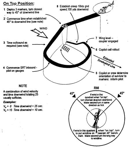 Wing awareness/lookout doctrine
Be aware of Wing so that you dont put him in a position of him looking into the sun at you. Wing be aware of your situation. Even though lead is in charge of that, Wing PNAC may be the ONLY person noticing the 500 fpm descent into the water because lead is doing something else.
Lookout doctrine: While it may be one of Leads responsibilities, both aircraft should keep a 360 ° overlapping lookout, giving you TWICE the set of eyes. WW/CAWW/Convective SIGMET/SIGMET/AIRMET
WW (Aviation Severe Weather Watch Bulletins)
National weather service issues whenever there is a high probability of severe weather. Except for operational necessity, emergencies, and flights involving all weather research projects or weather reconnaissance, pilots shall not file into or through areas that the National Weather Service has issued a WW unless one of the following exceptions apply:
A) Storm development has not progressed as forecast for the planned route.
Can be IFR if you have radar, or can stay VMC. (both to avoid bad stuff)
B) Performance characteristics of the aircraft permit an en route flight altitude above existing or developing severe storms
CAWW (CNATRA AVIATION WEATHER WATCH)
CAWW is issued by the NAVY to restrict training aircraft from flying through potentially hazardous conditions not severe enough to warrant the National Weather Service (NWS) to issue a WW.
WST (Convective SIGMETs)
Concern only thunderstorms and related phenomena (tornadoes, heavy precipitation, hail, and high surface winds) over the conterminous United States and imply the associated occurrence of turbulence, icing and convective low-level wind shear. They are issued hourly and are valid for up to 2 hours. WSTs shall be issued when either of the following occurs and/or is forecast to occur for more than 30 minutes of the valid period regardless of the size of the area affected (i.e., including isolated):
a. Tornadoes.
b. Lines of thunderstorms.
c. Embedded thunderstorms.
d. Thunderstorm areas greater than or equal to thunderstorm intensity (VIP LVL) of four (4) or greater with an area of coverage of 4/10 (40 percent) or more.
e. Hall greater than or equal to 3/4 inch in diameter or greater and/or wind gusts to fifty (50) knots or greater.
WS (Nonconvective SIGMETs)
Nonconvective SIGMETs relevant to areas within the conterminous U.S. are issued by (NAWAU) and valid for up to 4 hours, when any of the following weather phenomena occur or are forecast over an area of at least 3,000 square miles:
a. Severe or extreme nonconvective turbulence, or clear air turbulence (CAT) not associated with thunderstorms.
b. Severe icing not associated with thunderstorms
c. Widespread dust storms, sandstorms, or volcanic ash lowering surface and/or flight visibilities to less than 3 miles.
d. Volcanic eruption.
WA (AIRMETs)
AIRMETs are also advisories of significant weather phenomena but describe conditions at intensities lower than those which trigger SIGMETs. Describe phenomena the same as, or similar to, those requiring the issuance of nonconvective SIGMETs. Shall be issued on a scheduled basis every 6 hours beginning at 0200 UTC.
| Sorting Options | |
| 2016 | |
 Earrings!
12/26/2016 Earrings!
12/26/2016
|
|
 Rock Off
12/18/2016 Rock Off
12/18/2016
|
|
 Halloween 2016
10/31/2016 Halloween 2016
10/31/2016
|
|
 Dresser
10/16/2016 Dresser
10/16/2016
|
|
| 2012 | |
 Creating Cupcakes
12/22/2012 Creating Cupcakes
12/22/2012
|
|
 Kodiak Visit
10/4/2012 Kodiak Visit
10/4/2012
|
|
 San Francisco Visit
5/7/2012 San Francisco Visit
5/7/2012
|
|
 Custom iDock
1/28/2012 Custom iDock
1/28/2012
|
|
 New Van
1/5/2012 New Van
1/5/2012
|
|
| 2011 | |
 Emily's Video
10/28/2011 Emily's Video
10/28/2011
|
|
 Corpus Christi Visit
8/27/2011 Corpus Christi Visit
8/27/2011
|
|
 Port Angeles Visit
5/15/2011 Port Angeles Visit
5/15/2011
|
|
| Next Page |